17 gpio interface signals – AMD Geode SC1201 User Manual
Page 67
AMD Geode™ SC1200/SC1201 Processor Data Book
67
Signal Definitions
32579B
3.4.17
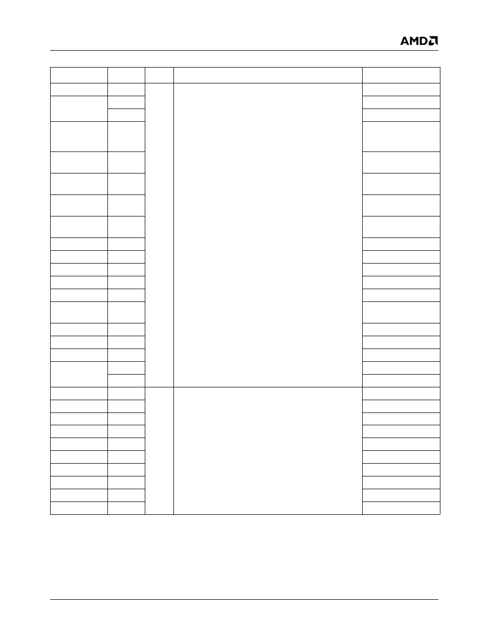
GPIO Interface Signals
Signal Name
Ball No.
Type
Description
Mux
GPIO0
D11
I/O
GPIO Port 0. Each signal is configured independently as
an input or I/O, with or without static pull-up, and with
either open-drain or totem-pole output type.
A debouncer and an interrupt can be enabled or masked
for each of signals GPIO[00:01] and [06:15] indepen-
dently.
Note:
GPIO12, GPIO13, GPIO16 inputs: If GPIOx func-
tion is selected but not used, tie GPIOx low.
TRDE#
GPIO1
D10
IOCS1#+TFTD12
N30
AB1D+IOCS1#
GPIO6
D28
DTR2#/BOUT2+
IDE_IOR1#+
SDTEST5
GPIO7
C30
RTS2#+IDE_DACK1#
+SDTEST0
GPIO8
C31
CTS2#+IDE_DREQ1
+SDTEST4
GPIO9
C28
DCD2#+IDE_IOW1#+
SDTEST2
GPIO10
B29
DSR2#+IDE_IORDY1
+SDTEST1
GPIO11
AJ8
RI2#+IRQ15
GPIO12
N29
AB2C
GPIO13
M29
AB2D
GPIO14
D9
IOR#+DOCR#
GPIO15
A8
IOW#+DOCW#
GPIO16
V31
PC_BEEP+
F_DEVSEL#
GPIO17
A10
IOCS0#+TFTDCK
GPIO18
AG1
DTR1#/BOUT1
GPIO19
C9
INTC#+IOCHRDY
GPIO20
A9
DOCCS#+TFTD0
N31
AB1C+DOCCS#
GPIO32
M28
I/O
GPIO Port 1. Each signal is configured independently as
an input or I/O, with or without static pull-up, and with
either open-drain or totem-pole output type.
A debouncer and an interrupt can be enabled or masked
for each of signals GPIO[32:41] independently.
LAD0
GPIO33
L31
LAD1
GPIO34
L30
LAD2
GPIO35
L29
LAD3
GPIO36
L28
LDRQ#
GPIO37
K31
LFRAME#
GPIO38/IRRX2
K28
LPCPD#
GPIO39
J31
SERIRQ
GPIO40
Y3
IDE_DATA8
GPIO41
W4
IDE_DATA11