Electrical specifications, 1 general specifications, 1 electro static discharge (esd) – AMD Geode SC1201 User Manual
Page 365: 2 power/ground connections and decoupling, 3 absolute maximum ratings, General specifications, Table 9-1, Electro static discharge (esd), Table 9-2, Absolute maximum ratings
AMD Geode™ SC1200/SC1201 Processor Data Book
365
9
Electrical Specifications
32579B
9.0
Electrical Specifications
This chapter provides information about:
• General electrical specifications
• DC characteristics
• AC characteristics
Note:
All voltage values in this chapter are with respect
to V
SS
unless otherwise noted.
9.1
General Specifications
9.1.1
Electro Static Discharge (ESD)
This device is a high performance integrated circuit and is
ESD sensitive. Handling and assembly of this device
should be performed at ESD free workstations. Table 9-1
lists the ESD ratings of the SC1200/SC1201 processor.
9.1.2
Power/Ground Connections and
Decoupling
When testing and operating the SC1200/SC1201 proces-
sor, use standard high frequency techniques to reduce par-
asitic effects. For example:
• Filter the DC power leads with low-inductance decou-
pling capacitors.
• Use low-impedance wiring.
• Utilizing the PWR and GND pins.
9.1.3
Absolute Maximum Ratings
Stresses beyond those indicated in the following table may
cause permanent damage to the SC1200/SC1201 proces-
sor, reduce device reliability and result in premature failure,
even when there is no immediately apparent sign of failure.
Prolonged exposure to conditions at or near the absolute
maximum ratings may also result in reduced device life
span and reduced reliability.
Note:
The values in the following table are stress ratings
only. They do not imply that operation under other
conditions is impossible.
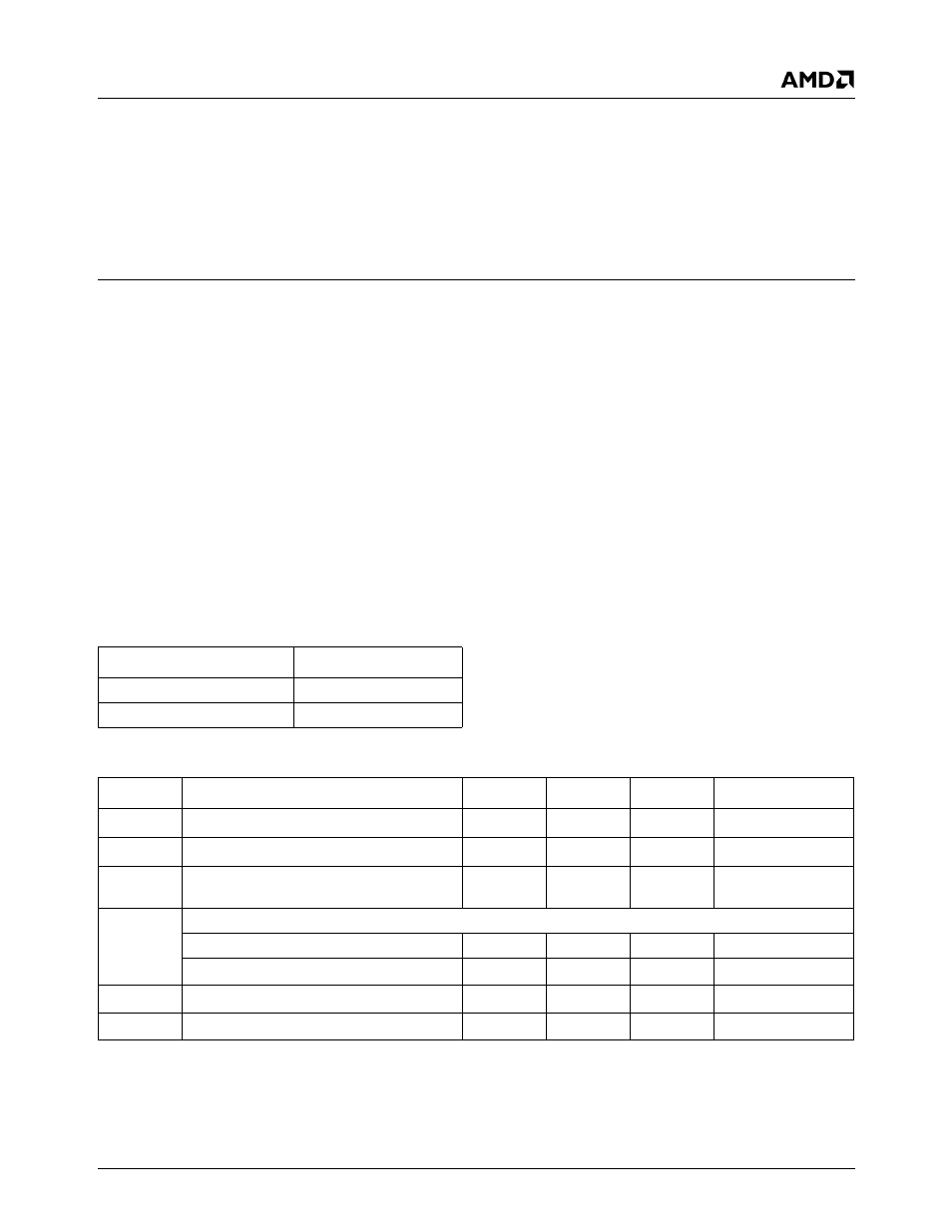
Table 9-1. Electro Static Discharge (ESD)
Parameter
Units
Human Body Model (HBM)
2000V ESD
Machine Model (MM)
200V ESD
Table 9-2. Absolute Maximum Ratings
Symbol
Parameter
Min
Max
Unit
Comments
T
CASE
Operating case temperature
-10
110
o
C
Note 1
T
STORAGE
Storage temperature
-45
125
o
C
Note 2
V
CC
Supply voltage
V
V
MAX
Voltage on
5V tolerant balls
-0.5
6.0
V
Note 3
Others
-0.5
3.6
V
Note 3, Note 4
I
IK
Input clamp current
-0.5
10
mA
Note 1
I
OK
Output clamp current
25
mA
Note 1
Note 1. Power applied - no clocks.
Note 2. No bias.
Note 3. Voltage min is -0.8V with a transient voltage of 20 ns or less.
Note 4. Voltage max is 4.0V with a transient voltage of 20 ns or less.