8 lpc interface, Figure 9-22, Lpc output timing diagram – AMD Geode SC1201 User Manual
Page 398: Figure 9-23, Lpc input timing diagram, Table 9-25, Lpc and serirq
398
AMD Geode™ SC1200/SC1201 Processor Data Book
Electrical Specifications
32579B
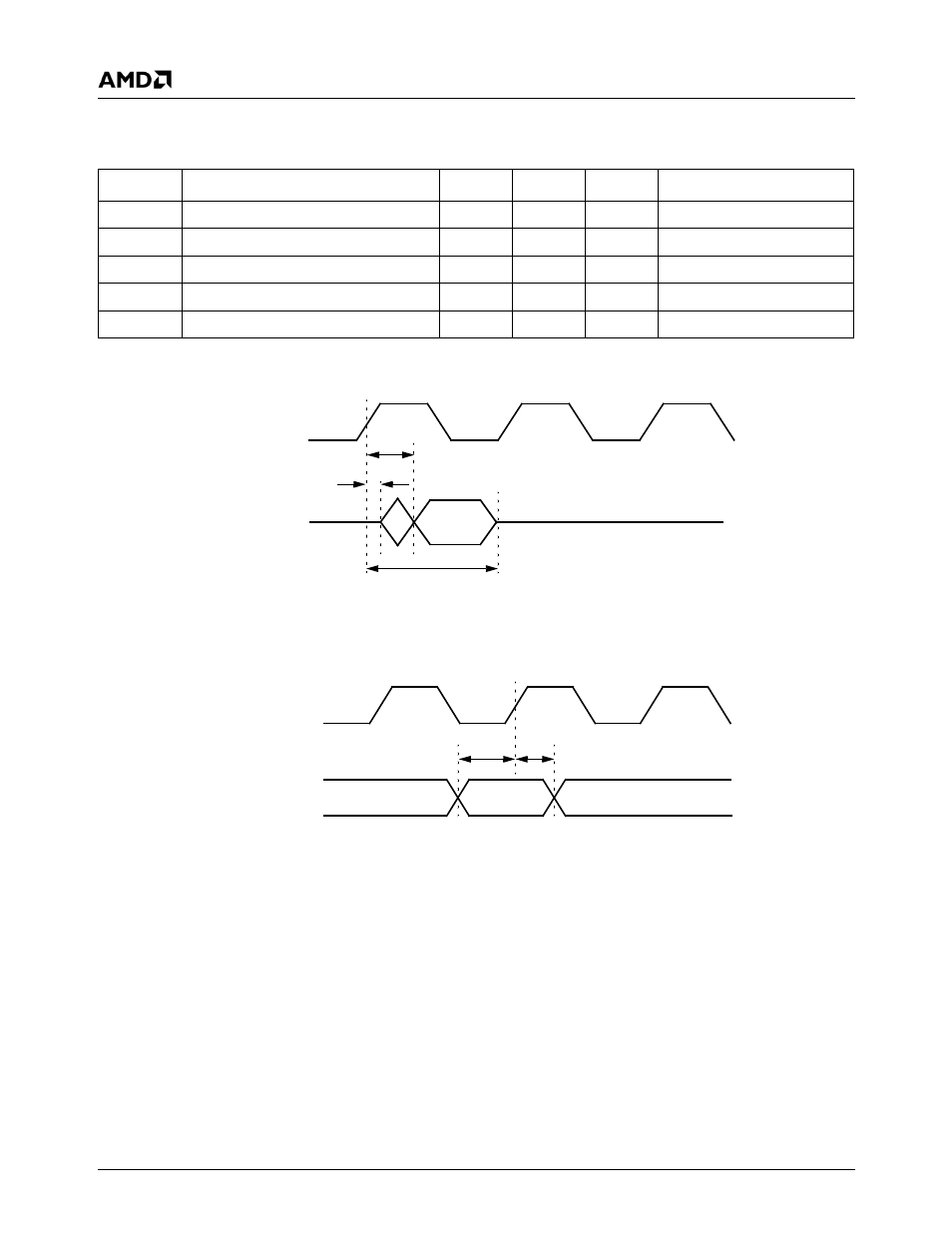
9.3.8
LPC Interface
Figure 9-22. LPC Output Timing Diagram
Figure 9-23. LPC Input Timing Diagram
Table 9-25. LPC and SERIRQ
Symbol
Parameter
Min
Max
Unit
Comments
t
VAL
Output Valid delay
0
17
ns
After PCICLK rising edge
t
ON
Float to Active delay
2
ns
After PCICLK rising edge
t
OFF
Active to Float delay
28
ns
After PCICLK rising edge
t
SU
Input Setup time
7
ns
Before PCICLK rising edge
t
HI
Input Hold time
0
ns
After PCICLK rising edge
PCICLK
LPC Signals/
SERIRQ
t
ON
t
VAL
t
OFF
PCICLK
LPC Signals/
SERIRQ
t
SU
t
HI
Input
Valid
This manual is related to the following products: