12 fast ir port timing, Figure 9-43, Fast ir timing (mir and fir) diagram – AMD Geode SC1201 User Manual
Page 422: Table 9-33, Fast ir port timing parameters
422
AMD Geode™ SC1200/SC1201 Processor Data Book
Electrical Specifications
32579B
9.3.12
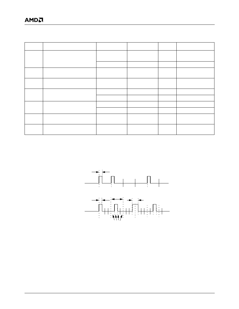
Fast IR Port Timing
Figure 9-43. Fast IR Timing (MIR and FIR) Diagram
Table 9-33. Fast IR Port Timing Parameters
Symbol
Parameter
Min
Max
Unit
Comments
t
MPW
MIR signal pulse width
t
MWN
-25
(Note 1)
t
MWN
+25
ns
Transmitter
60
ns
Receiver
M
DRT
MIR transmitter data rate
tolerance
± 0.1%
t
MJT
MIR receiver edge jitter, % of
nominal bit duration
± 2.9%
t
FPW
FIR signal pulse width
120
130
ns
Transmitter
90
160
ns
Receiver
t
FDPW
FIR signal double pulse width
245
255
ns
Transmitter
215
285
ns
Receiver
F
DRT
FIR transmitter data rate
tolerance
± 0.01%
t
FJT
FIR receiver edge jitter, % of
nominal bit duration
± 4.0%
Note 1. t
MWN
is the nominal pulse width for MIR mode. It is determined by the M_PWID field (bits [4:0]) in the MIR_PW
register at offset 01h in bank 6 of logical device 5.
t
FPW
Data
MIR
FIR
Symbol
t
FDPW
Chips
t
MPW