1 measurement and test conditions, Figure 9-17, Pci output timing measurement conditions – AMD Geode SC1201 User Manual
Page 392: Table 9-23, Measurement condition parameters
392
AMD Geode™ SC1200/SC1201 Processor Data Book
Electrical Specifications
32579B
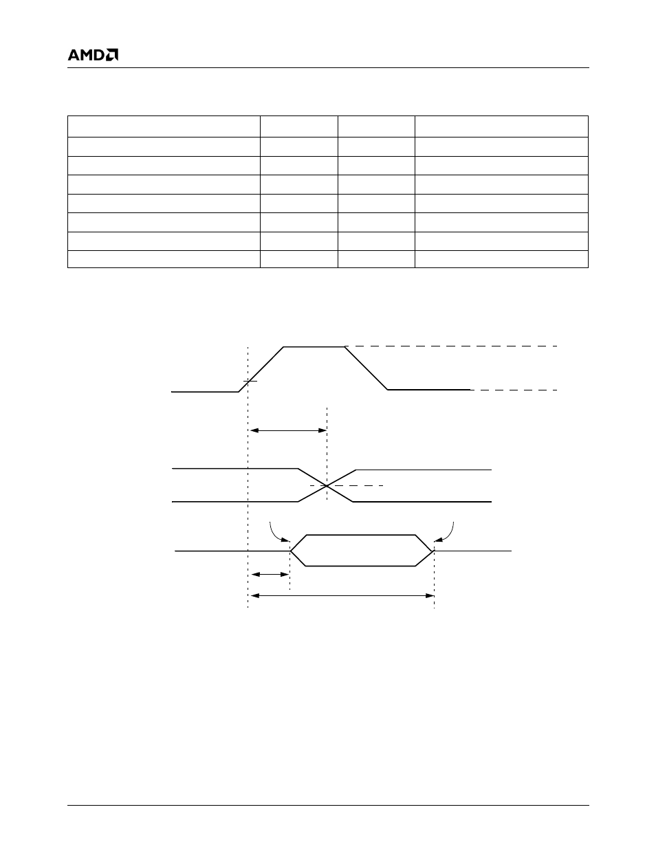
9.3.6.1
Measurement and Test Conditions
Figure 9-17. PCI Output Timing Measurement Conditions
Table 9-23. Measurement Condition Parameters
Symbol
Value
Unit
Comments
V
TH
0.6 V
IO
V
Note 1
V
TL
0.2 V
IO
V
Note 1
V
TEST
0.4 V
IO
V
V
STEP
(rising edge)
0.285 V
IO
V
V
STEP
(falling edge)
0.615 V
IO
V
V
MAX
0.4 V
IO
V
Note 2
Input signal edge rate
1
V/ns
Note 1. The input test is performed with 0.1 V
IO
of overdrive. Timing parameters must not exceed this overdrive.
Note 2. V
MAX
specifies the maximum peak-to-peak waveform allowed for measuring input timing.
Output Current
≤ Leakage Current
t
OFF
t
ON
PCICLK
Output
Delay
TRI-STATE
Output
V
TH
V
TL
V
TEST
V
STEP
t
VAL
This manual is related to the following products: