Campbell Scientific CR9000X Measurement and Control System User Manual
Page 92
Section 3. CR9000X Measurement Details
The CR9000X incorporates a programmable gain input instrumentation
amplifier, as illustrated in FIGURE 3.1.2-1. The voltage gain of the
instrumentation amplifier is determined by the user selected range code
associated with voltage measurement instructions. The instrumentation
amplifier can be configured to measure either single-ended (SE) or differential
(DIFF) voltages.
For SE measurements the voltage to be measured is connected to the H input
while the L input is internally connected to the signal ground ( ) on the
wiring panel. CRBasic instructions BRHalf, BRHalf6W, TCSE, and VoltSE
perform Single Ended voltage measurements.
For DIFF measurements, the voltage to be measured is connected between the
H and L inputs on the instrumentation amplifier. CRBasic instructions
BrFull(), BrFull6W(), BrHalf4W(), TCDiff(), and VoltDiff() perform DIFF
voltage measurements.
FIGURE 3.1.2-1. Programmable gain instrumentation amplifier
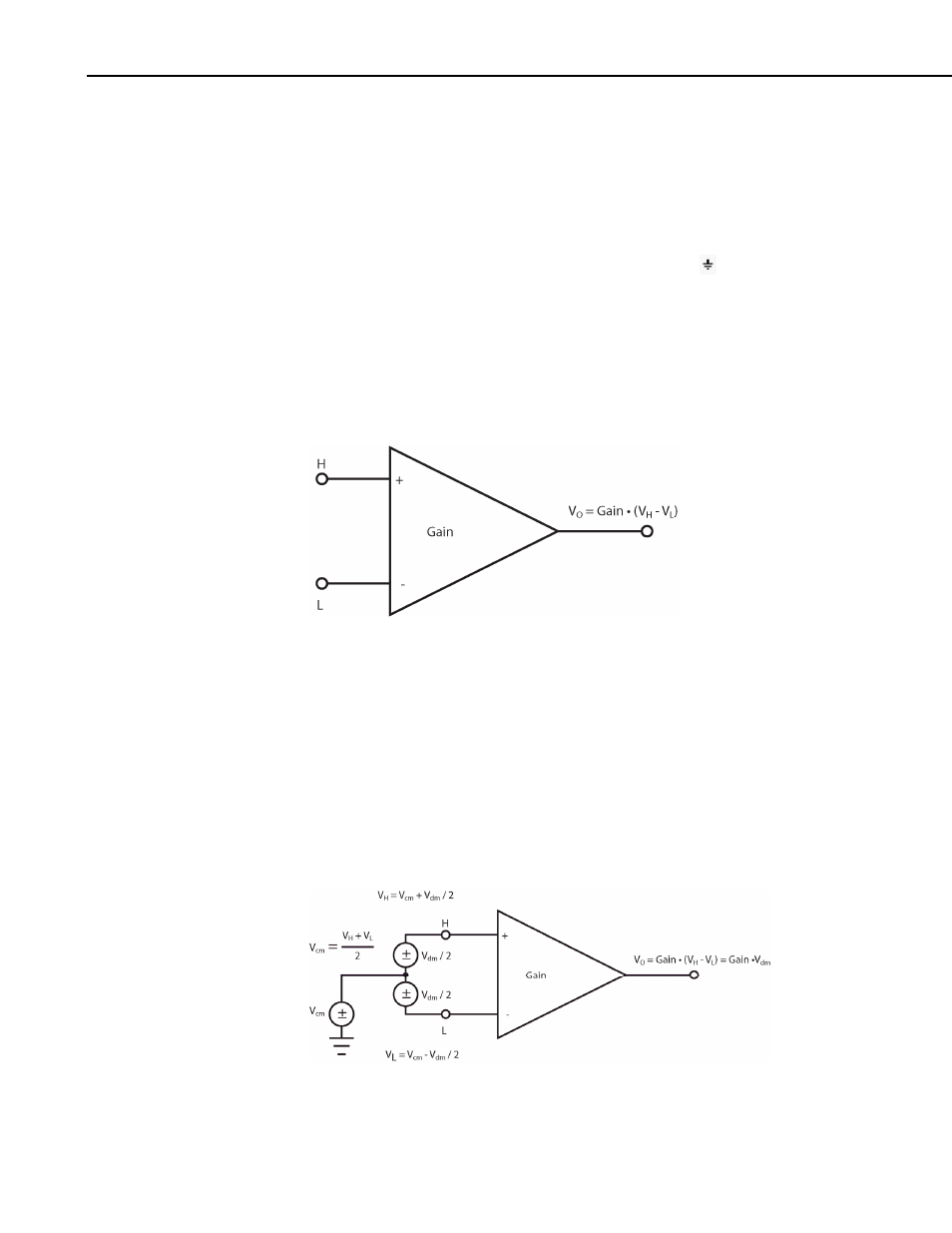
An instrumentation amplifier processes the difference between the H and L
inputs, while rejecting voltages that are common to both with respect to the
CR9000X ground. FIGURE 3.1.2-2 illustrates the instrumentation amplifier
with the input signal decomposed into a common-mode voltage (V
cm
) and a
DIFF mode voltage (V
dm
). The common-mode voltage is the average of the
voltages on the H and L inputs, i.e., V
cm
= (V
H
+ V
L
)/2, which can viewed as
the voltage remaining on both the H and L inputs when the DIFF voltage
(V
dm
) equals 0. The voltage on the H and L inputs is given as V
H
= V
cm
+
V
dm
/2, and V
L
= V
cm
– V
dm
/2, respectively.
FIGURE 3.1.2-2. Programmable gain instrumentation amplifier with
input signal decomposition
3-4