R*: cr9058e – Campbell Scientific CR9000X Measurement and Control System User Manual
Page 228
Section 7. Measurement Instructions
7-4
Place an R at the end of the range code (ex: mV50CR) in order to
perform an Input Voltage Limit check before making the measurement.
If the input is out of Input Voltage Limit, a NAN will be returned.
Example: VoltDiff (Dest,Reps,mV50CR,ASlot,Channel,True,Settle,Integ,Mult,Offset)
See Section 3.1.2.2 Diff. Voltage Range
for details on the R, Input Limit
check, option.
Enter -1, -2, -3, -4 or -5 for the integration parameter when using a
CR9058E and the filter order will be set to 1, 2, 3, 4, or 5. The
integration time will automatically be set to the maximum allowed for
the given Scan Interval and filter order.
See Section 3.2 CR9058E Isolation Module Measurements for details.
Remarks: With a multiplier of 1 and an offset of 0, the result is in millivolts or
volts depending on the range selected. This instruction measures the voltage
difference between the High and Low inputs of a differential channel. Both
the high and low inputs must be within ± 5V of the datalogger's ground.
See the Input Limits Topic in Section 3.1.2 SE and DIFF Voltage
Measurements.
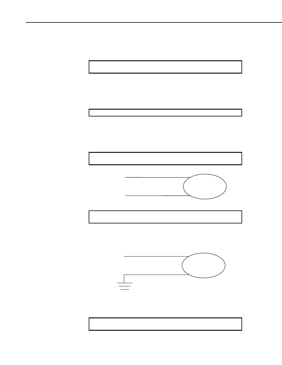
Sensor
Diff. Channel H
Diff. Channel L
.
See Section 3.1.2.2 Differential Voltage Range for in-depth coverage of the
Differential Measurement process.
VoltSE (Dest, Reps, Range, ASlot, SEChan, SettlingTime, Integ, Mult,
Offset)
Sensor
S.E. Channel
Ground
This instruction measures the voltage at a single ended input with respect to
ground. With a multiplier of one and an offset of 0, the result is in millivolts
or volts depending on the range selected.
See Section 3.1.2.1 Single Ended Voltage Range for in-depth coverage of the
Single Ended Measurement process.
R*:
CR9058E*: