5 bridge resistance measurements – Campbell Scientific CR9000X Measurement and Control System User Manual
Page 106
Section 3. CR9000X Measurement Details
CR9000
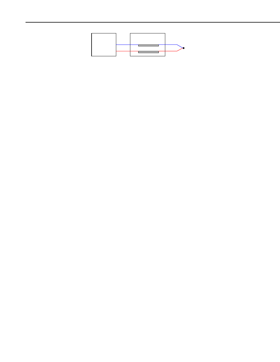
H
L
A'
A
B'
B
Junction Box
TC
FIGURE 3.1.4-2. Diagram of junction box
An external reference junction box must be constructed so that the entire
terminal area is very close to the same temperature. This is necessary so that a
valid reference temperature can be measured and to avoid a thermoelectric
offset voltage which will be induced if the terminals at which the thermocouple
leads are connected (points A and B in Figure 3.4-1) are at different
temperatures. The box should contain elements of high thermal conductivity,
which will act to rapidly equilibrate any thermal gradients to which the box is
subjected. It is not necessary to design a constant temperature box, it is
desirable that the box respond slowly to external temperature fluctuations.
Radiation shielding must be provided when a junction box is installed in the
field. Care must also be taken that a thermal gradient is not induced by
conduction through the incoming wires. The CR9000X can be used to
measure the temperature gradients within the junction box.
3.1.5 Bridge Resistance Measurements
There are five bridge measurement instructions included in the standard
CR9000X software. Figure 3.5-1 shows the circuits that would typically be
measured with these instructions. In the diagrams, X is the result from the
measurement, the resistors labeled R
s
would normally be the sensors and those
labeled R
f
would normally be fixed resistors. Circuits other than those
diagrammed could be measured, provided the excitation and type of
measurements were appropriate.
All of the bridge measurements have the option (RevEx) to make one set of
measurements with the excitation as programmed and another set of
measurements with the excitation polarity reversed. The offset error in the two
measurements due to thermal emfs can then be accounted for in the processing
of the measurement instruction. The excitation channel maintains the
excitation voltage until the hold for the analog to digital conversion is
completed. When more than one measurement per sensor is necessary (four
wire half bridge, three wire half bridge, six wire full bridge), excitation is
applied separately for each measurement. For example, in the four wire half
bridge when the excitation is reversed, the differential measurement of the
voltage drop across the sensor is made with the excitation at both polarities and
then excitation is again applied and reversed for the measurement of the
voltage drop across the fixed resistor.
Calculating the actual resistance of a sensor which is one of the legs of a
resistive bridge usually requires additional processing following the bridge
measurement instruction. In addition to the schematics of the typical bridge
configurations, Figure 3.1.5-1 lists the calculations necessary to compute the
resistance of any single resistor, provided the values of the other resistors in
the bridge circuit are known.
3-18