Cr9032 cpu module – Campbell Scientific CR9000X Measurement and Control System User Manual
Page 36
Overview
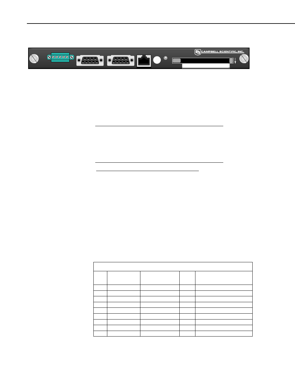
CR9032 CPU Module
CR9032 CPU
RS-232
CS I/O
ETHERNET
CARD
PC-CARD
MADE IN USA
STATUS
Top of Card Faces Down
CONTROL
SDM
+12 G C1 C2 C3
FIGURE OV1-2. CR9032
The CR9032 CPU Module provides system control, processing, and
communication. The CR9032 CPU module is the main processor for the
datalogger as well as memory for program storage and buffering data. The
main processor is a 180 MHz Hitachi SH-4 microprocessor. The module has
128 MB SDRAM and 2 MB Flash EEPROM. 128 KB of the Flash memory is
reserved for program storage.
The 128 MB of SDRAM is not battery backed and that data that
is stored there will be lost when the logger is powered down or
experiences a watchdog reset.
NOTE
CRITICAL DATA SHOULD BE STORED ON THE
PCMCIA CARD.
The CR9032 CPU Module provides the following:
SDM Ports C1 through C3 are used for communication with SDM (Synchronous Device
for Measurements) peripherals such as the SDM-CAN or SDM-SIO4. The
SDM 12 volt supply is current limited to 1.85 amps and can be used to power
other peripherals besides SDM devices.
RS232
The Datalogger RS-232 port can function as either a DCE (Data
Communication Equipment such as a modem) or DTE (Data Terminal
Equipment such as a computer) device. For the Datalogger RS-232 port to
function as a DTE device, a null modem cable is required. The most common
use of the Datalogger's RS-232 port is a connection to a computer DTE device.
A standard DB9-to-DB9 cable can connect the computer DTE device to the
Datalogger DCE device. Pins 1, 4, 6 and 9 function differently than a standard
DCE device. This is to accommodate a connection to a modem or other DCE
device via a null modem. Pin configuration for the CR9000X RS-232 9-pin
port is listed in TABLE OV1-1.
TABLE OV1-1. Datalogger RS-232 Pin-Out
PIN
DCE
Function
Logger
Function
I/O
Description
1
DCD
DTR (tied to pin 6)
O*
Data Terminal Ready
2
TXD
TXD
O
Asynchronous data Transmit
3
RXD
RXD
I
Asynchronous data Receive
4 DTR
N/A X* Not
Connected
5 GND
GND GND
Ground
6
DSR
DTR
O*
Data Terminal Ready
7
CTS
CTS
I
Clear to send
8
RTS
RTS
O
Request to send
9 RI
RI I*
Ring
OV-4