Overview – Campbell Scientific CR9000X Measurement and Control System User Manual
Page 48
Overview
CR9070 Counter - Timer / Digital I/O Module — Obsolete
9070 COUNTER & DIGITAL I O
1
2
DIGITAL I/O
4
5
7
8
9
10
12
13
15
16
1
2
3
4
5
6
7
8
9
10
11
12
MADE IN USA
3
6
11
14
LOW LEVEL AC
SWITCH CLOSURRE
FIGURE OV1-12. 9070
The CR9070 has been replaced by the CR9071E, which provides better over-
voltage protection, increased channel-to-channel cross-talk isolation, interval
(edge) timing with 40 nanosecond resolution, and a Wait Digital Trigger
function.
The CR9070 Pulse Module has 16 Digital I/O channels and 12 Pulse channels
with 16 bit accumulators. The CR9070 is used for Pulse measurements, as
well as state monitoring and control.
CHANNEL DESCRIPTION
Digital I/O
The CR9070 has 16 Digital I/O ports selectable, under program control, as
binary inputs or control outputs. These ports have multiple function capability
including: edge timing, TTL signal period or frequency measurements, device
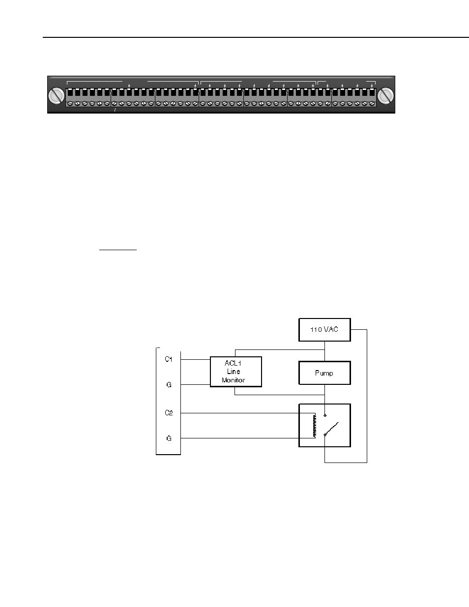
driven interrupts, and, as shown in Figure OV1-13, state monitoring and
control (i.e.: turning on/off devices and monitoring whether the device is On or
Off). The Edge Timing resolution is limited to the logger's Scan Interval.
Digital I/O Ports Used to Control/Monitor Pump
C1 - Used as input to monitor pump status.
C2 - Used as output to switch power to a pump via a solid state relay.
FIGURE OV1-13. Control and monitoring of a device using digital I/O
ports
OV-16