Campbell Scientific CR9000X Measurement and Control System User Manual
Page 369
Section 9. Program Control Instructions
Combing the two equations above results in the equations used for calculating
the simulated strain that is induced by the shunt resistor:
με
S
G
G
S
R
R
R
G
=
−
Ч
+
Ч
10
6
(
)
F
Variable definitions:
με
S
=
Simulated micro-strain created by shunt resistor
R
S
= Shunt resistor resistance (ohms)
R
G
= Nominal gauge resistance (ohms)
GF
=
Gauge
factor
This simulated strain value will be calculated by the logger.
The datalogger will compare the calculated strain,
με
S
,
to the strain value,
με
R
,
which is the change, in microstrain, of the measurement from the
unshunted to the shunted conditions. A multiplier is derived from the ratio,
με
R
/
με
S
.
The arm of the bridge that is being shunted (entered by setting the
sign of the entered shunt resistance value), will be used to determine the sign
of this multiplier to insure that the polarity of the output is correct.
The raw gauge factor is multiplied by this factor to derive an adjusted gauge
factor for the system,
GF
C
= GF x
με
R
/
με
S
,
that is used to correct the output
from the instrumentation.
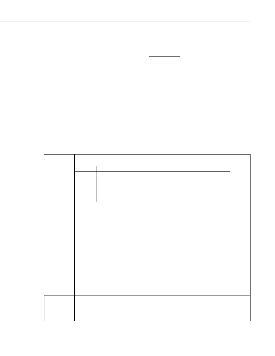
Parameter
Enter
FIELDCALSTRAIN PARAMETERS
Used to specify the type of calibration that will be performed.
Digit Function
10 Zero
Function
13
Shunt calibration, 1/4 Bridge Strain:
33
Shunt Calibration, Half bridge strain gauge, one gage parallel to
+ε
, the other
parallel to
−ε
:
Function
Integer
43
Shunt Calibration, Full bridge strain gage, 2 gages parallel to
+ε
, the other 2
parallel to
−ε
MeasureVar
Variable
Zero calibration: The variable or variable array that holds the raw mV per volt output from
the Bridge measurement that is used as the source feed into the StrainCalc instruction for the
gauge(s) being calibrated.
Shunt calibration: The variable or variable array that holds the calculated micro-strain results
from the StrainCalc instruction for the gauge(s) being calibrated.
For either zeroing or shunt calibration, the MeasureVar array must be dimensioned large
enough to accommodate the number of Reps.
Reps
Constant or
Variable
Specifies the number of sensors to that will be setup for calibration.
Note: Must be set to 1 or the number of elements in the MeasureVar parameter array.
When Reps is equal to the size of the MeasureVar parameter (Index parameter must be set to
1), all elements of the MeasureVar array will be calibrated in a single scan.
When Reps is set to 1, a single element of the MeasureVar array, specified by the Index
parameter, will be calibrated.
Reps is usually set to 1 when doing shunt calibrations, and set to the number of elements in
the MeasureVar when setting up Zero calibrations. If the Reps parameter is declared as a
variable, the value can be changed during program operation. This allows the calibration of a
complete array at one point, and following up later with a calibration on a single element of
the array. If Reps is set to zero, no calibration will occur for this instruction.
GFAdj
Variable
(array)
Zero calibration: Zero can be entered for this parameter (not used).
Shunt calibration: Variable or variable array that is populated with the computed gage
factors used in the StrainCalc instruction for computing the micro-strain. It should be
dimensioned large enough to hold values for all of the elements of the MeasVar parameter.
GFAdj is set equal to GF_Raw during the calibration process.
9-39