2 system power requirements and options, 1 power supply and charging circuitry – Campbell Scientific CR9000X Measurement and Control System User Manual
Page 65
Section 1. Installation
1.2 System Power Requirements and Options
The standard CR9000X is equipped with two sealed lead acid battery packs
and charging circuitry for charging the batteries from a 9-18 volt DC input.
The charging input can come from 120/240 VAC line power via the universal
AC power adapter (included with CR9000X), vehicular 12 V power sources,
solar panels, et cetera. When fully charged, the internal batteries of the
CR9000X are capable of providing 13-14 Amp-hours, between 4 and 13 hours
of operation in a typical application where the CR9000X is active continuously
(not powering itself down).
1.2.1 Power Supply and Charging Circuitry
The CR9011 Power Supply Module has two CHARGE inputs, wired in
parallel, for connecting a DC Power source: either the plug connector used
with the AC adapter or the screw terminals. A DC source with voltage in the
range of 9 to 18 VDC will charge the internal lead acid batteries and power
CR9000X provided sufficient current is available and the system is setup to
use 3 amps or less (see Table 1.2-2 Current required by CR9000X modules).
If the CR9000X system configuration requires greater than 3 amps, consult a
Campbell Scientific applications engineer for information on the CR9011
Power Supply High-Current modification. The voltage is automatically
stepped up to an adequate voltage for charging. A temperature compensated
charging regulator circuit regulates the charging voltage supplied to the lead
acid batteries and the CR9000X. The charging circuitry operates with the
ON/OFF switch in either position. The charging circuitry is NOT designed to
charge a large external 12 V battery as it is current limited to 2 amps.
Power for running the CR9000X and charging the internal batteries from AC
line power can be provided via the CR9000X's universal AC adapter through
the power input connector located on the 9011 Power Supply Module. The
universal adapter converts 100–240 VAC 50–60 Hz to 17.5 VDC.
On the left end of the Power Supply Module there are two LEDs: Power and
Charge. The charge LED is lit when there is sufficient power connected to
charge the batteries. Power to the CR9000X is controlled by the ON/OFF
toggle switch. The power LED is lit when the CR9000X is on. It goes off
when the switch is in the off position, when the CR9000X is powered off
under program control (PowerOff instruction), or when there is insufficient
voltage to run the system.
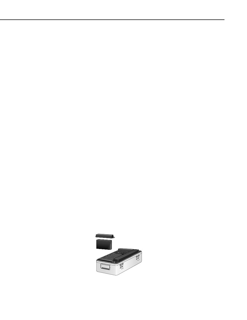
The lead acid battery packs are located at each end of the CR9000X (Figure
1.2-1).
CR9000
FIGURE 1.2-1. CR9000X battery pack
1-3