Campbell Scientific CR9000X Measurement and Control System User Manual
Page 40
Overview
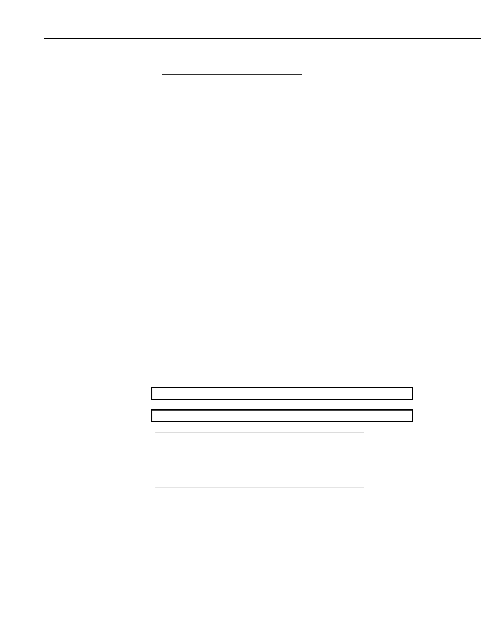
Full Scale
Maximum
Range
Resolution
Throughput
± 5000 mV
158 uV
100 KHz
± 1000 mV
32 uV
100 KHz
± 200 mV
6.3 uV
100 KHz
± 50 mV
1.6 uV
50 KHz
The CR9050(E) operational input voltage limits are ± 5 volts with reference to
datalogger ground. Voltages exceeding
±9 V with reference to datalogger
ground may cause errors on other channels. When the logger is powered off,
the CR9050(E)'s input impedance drops drastically.
The CR9050(E) contains an on-board PRT, located at the top center of the
module, which provides the reference temperature for thermocouple
measurements. A heavy copper grounding bar and connectors combined with
the aluminum case help to reduce temperature gradients for accurate
thermocouple measurements. If the logger is in an environment that is
experiencing rapid temperature fluctuations, it is recommended that the
CR9000X be insulated to reduce the temperature gradient along the copper bar.
This is true for all modules used to measure thermocouples.
CR9050 SUPPORTED MEASUREMENT INSTRUCTIONS:
Voltage
VoltDiff
Differential Voltage
VoltSe
Single-Ended Voltage
TCDiff
Differential Thermocouple
TCSE
Single Ended Thermocouple
Bridge measurements (also requires CR9060 Excitation Module)
BrFull Full
Bridge
BrFull6W
6 Wire Full Bridge
BrHalf
Half Bridge
BrHalf3W
3 Wire Half Bridge
BrHalf4W
4 Wire Half Bridge
Self measurements (reference PRT for thermocouple measurements)
ModuleTemp Module Temperature
See Section 3.1 Measurements using the CR9041 A/D for measurement details.
See Section 7 Measurement Instructions for Instruction details.
The CR9051E is recommended over the CR9050E for
applications where fault voltages beyond
±9 V could come in
contact with the inputs, or when the CR9000X could be powered
off while still connected to sensors that have power applied to
them.
NOTE
OV-8