Full bridge strain – Campbell Scientific CR9000X Measurement and Control System User Manual
Page 325
Section 8. Processing and Math Instructions
If the excitation voltage polarity is reversed, or the output polarity is reversed,
or if the output data needs to be positive when the G2 strain gauge sees positive
strain, then a positive Option (2) should be inserted into the Code parameter.
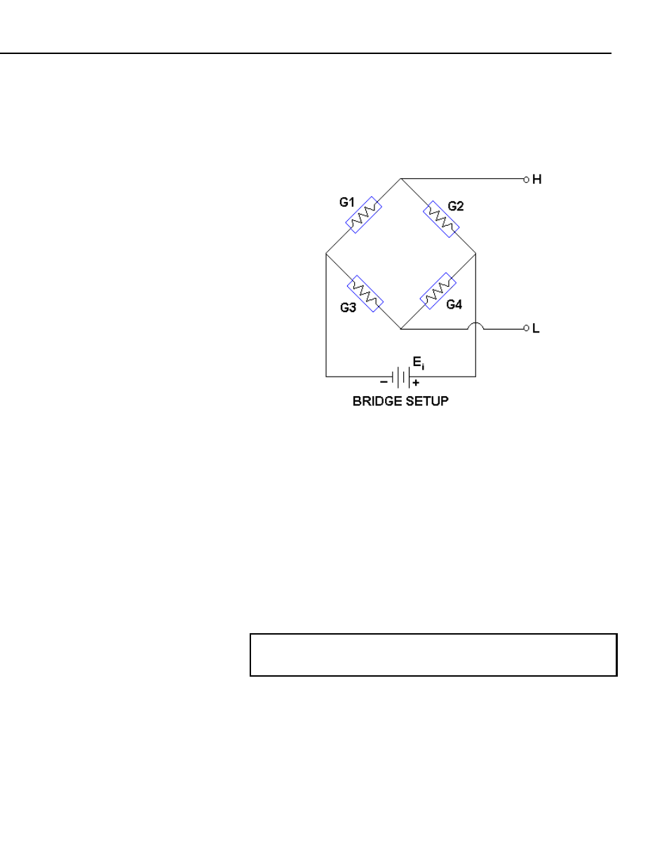
Full Bridge Strain
This example assumes that the bridge (shown above) is set up such that the
strain is considered to be positive when the G1 and G4 strain gauges experience
positive strain (tension) while the G2 and G3 strain gauges experience negative
strain (compression). In other words, when G1 and G4 increase in resistance
(while G2 and G3 decrease in resistance), the strain is considered to be positive.
For this set up, a negative number should be used for the BrConfig Option in
order for the CR9000X to output positive strain values when the G1 strain
gauge experiences positive strain. The default setting for the output was
configured for this bridge setup, and the CR9000X output strain data will be
positive when the G1 and G4 strain gauges experiences positive strain.
If the excitation voltage polarity is reversed, the output polarity is reversed, or if
the output data needs to be positive when the G2 and G3 strain gauges
experience positive strain, then Reverse should be clicked on.
See the FieldCalStrain Topic in Section 9.2 Data Logger Status/ Control for
information on both Zeroing and Shunt Calibration in conjunction with the
StrainCalc instruction.
8-39