21 1 f v v – Campbell Scientific CR9000X Measurement and Control System User Manual
Page 127
Section 3. CR9000X Measurement Details
circuit, a larger input voltage transition is required for higher frequencies. The
transition required for the input of the Schmitt trigger can be viewed as 2.5
volts
±
1 volt (from below 1.5 volt to above 3.5 volt). The equation to
calculate the amount that the signal is attenuated by the front end filter is:
( )
(
)
(
)
2
2
1
1
f
V
V
In
Out
πτ
+
=
V
Out
is the voltage level leaving the filter (level into the Schmitt circuit) when
V
In
is the input voltage. V
Out
must be at minimum 1 volt for the Schmitt
circuit to trigger an output.
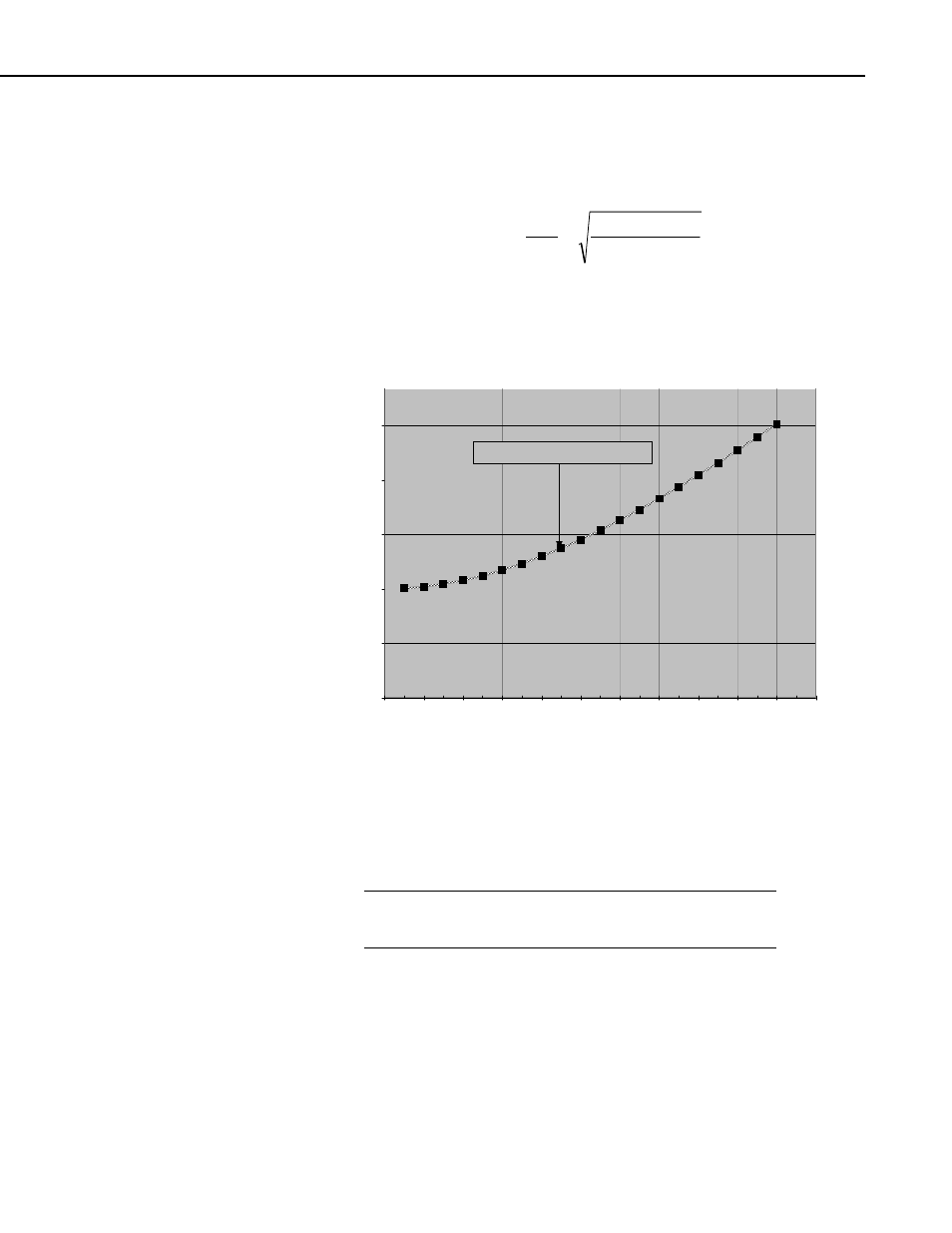
Chart 3.4.4-1 Required Transition Voltage for High Frequency Pulse
0.6
0.8
1
1.2
1.4
1.6
0
100000
200000
300000
400000
500000
600000
700000
800000
900000 1000000 1100000
Signal Frequency ( Hz)
±V Transistion (Centered at 2.5 Volt)
RequiredTransition Voltage
Chart 3.4.4-1 plots the trace for the minimum transition voltage about 2.5 volts
against the input signal frequency. To demonstrate how to use this plot, for a
input frequency of 1 MHz, the voltage signal, centered about 2.5 volts, must
have a transition of
±
1.6 volts in order to trigger the Schmitt circuit. In other
words, the signal must rise from below 0.9 volts (2.5 volts minus 1.6 volts) to
above 4.1 volts (2.5 volts plus 1.6 volts) for a pulse to be counted.
The input voltage range for the Pulse channels is
±
20 V.
Voltages outside of this range can damage the logger.
NOTE
I/O 1 – 16
When using the CR9071E's I/O ports for pulse timing (TimerIO instruction),
the positive threshold voltage is 3.5 V and the negative threshold voltage is 1
V. The maximum input voltage allowed is 5.5 volts and the minimum voltage
allowed is -0.5 V. Voltages outside of this range can damage the CR9071E.
3-39