5 powering sensors and devices, Figure 30: connecting to vehicle power supply, Table 4. current source and sink limits – Campbell Scientific CR1000 Measurement and Control System User Manual
Page 84
Section 7. Installation
84
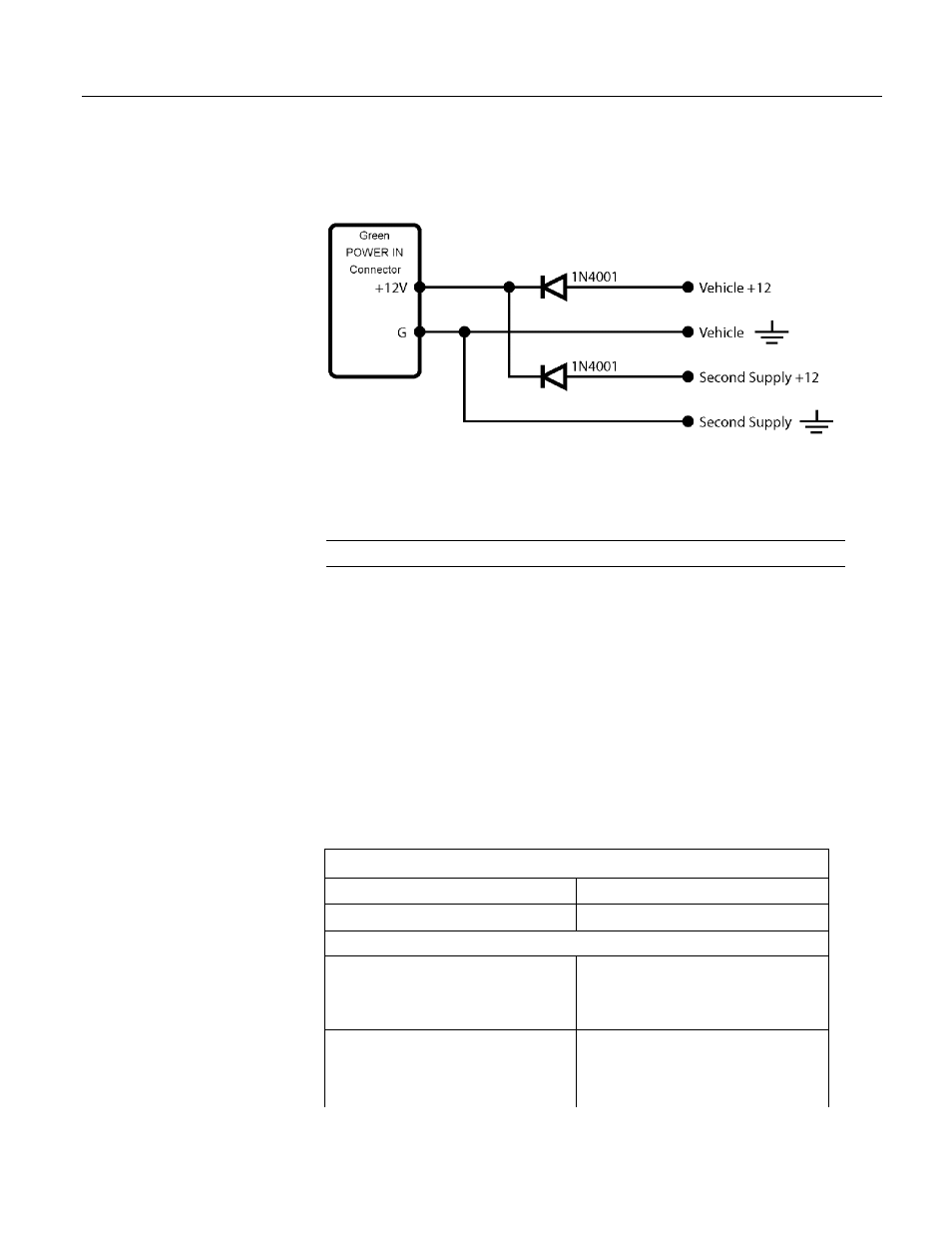
with the largest voltage to power the CR1000 and prevents the second backup
supply from attempting to power the vehicle.
Figure 30: Connecting to vehicle power supply
7.4.5 Powering Sensors and Devices
Read More! See Power Sources
(p. 82).
The CR1000 wiring panel is a convenient power distribution device for powering
sensors and peripherals that require a 5- or 12-Vdc source. It has 2 continuous 12-
Vdc terminals (12V), one program-controlled switched 12 Vdc terminal (SW-12),
and one continuous 5 Vdc terminal (5V). SW-12, 12V, and 5V terminals limit
current internally for protection against accidental short circuits. Voltage on the
12V and SW-12 terminals can vary widely and will fluctuate with the dc supply
used to power the CR1000, so be careful to match the datalogger power supply to
the requirements of the sensors. The 5V terminal is internally regulated to within
±4%, which is good regulation as a power source, but typically not adequate
accuracy for bridge sensor excitation. Table Current Sourcing Limits
(p. 84)
lists the
current limits of 12V and 5V. Greatly reduced output voltages associated with
12V, SW-12, and 5V due to current limiting may occur if the current limits given
in the table are exceeded. Information concerning digital I/O control ports is
available in Digital I/O Ports
(p. 327).
Table 4. Current Source and Sink Limits
Terminal
Limit
1
VX or EX (voltage excitation)
2
±25 mA maximum
SW-12
3
< 900 mA @ 20°C
< 630 mA @ 50°C
< 450 mA @ 70°C
12V + SW-12 (combined)
4
< 3.00 A @ 20°C
< 2.34 A @ 50°C
< 1.80 A @ 70°C