1 quarter-bridge shunt (option 13), 2 quarter-bridge zero (option 10) – Campbell Scientific CR1000 Measurement and Control System User Manual
Page 165
Section 7. Installation
165
7.8.1.6.1 Quarter-Bridge Shunt (Option 13)
With CRBasic example FieldCalStrain() Calibration Demo
(p. 164)
sent to the
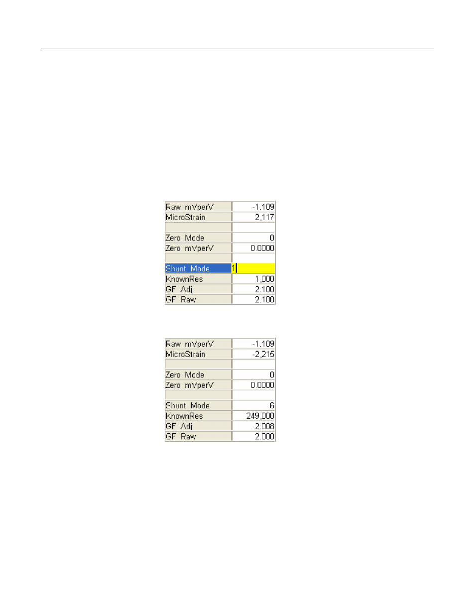
CR1000, and the strain gage stable, use the external keyboard / display or
software numeric monitor to change the value in variable KnownRes to the
nominal resistance of the gage, 1000 Ω, as shown in figure Strain-Gage Shunt
Calibration Started
(p. 165).
Set Shunt_Mode to 1 to start the two-point shunt
calibration. When Shunt_Mode increments to 3, the first step is complete.
To complete the calibration, shunt R1 with the 249-kΩ resistor. Set variable
KnownRes to 249000. As shown in figure Strain-Gage Shunt Calibration
Finished
(p. 165),
set Shunt_Mode to 4. When Shunt_Mode = 6, shunt calibration
is complete.
Figure 50: Strain-gage shunt calibration started
Figure 51: Strain-gage shunt calibration finished
7.8.1.6.2 Quarter-Bridge Zero (Option 10)
Continuing from Quarter-Bridge Shunt (Option 13)
(p. 165),
keep the 249-kΩ
resistor in place to simulate a strain. Using the external keyboard / display or
software numeric monitor, change the value in variable Zero_Mode to 1 to start
the zero calibration as shown in figure Starting Zero Procedure (p. 166). When
Zero_Mode increments to 6, zero calibration is complete as shown in figure Zero
Procedure Finished
(p. 166).