3 pulse measurement tips – Campbell Scientific CR1000 Measurement and Control System User Manual
Page 317
Section 8. Operation
317
8.1.5.3 Pulse Measurement Tips
• The PulseCount() instruction, whether measuring pulse inputs on pulse
channels (P1 through P2) or on digital I/O channels (C1 – C8), uses
dedicated 24-bit counters to accumulate all counts over the user-specified
scan interval. The resolution of pulse counters is one count or 1 Hz.
Counters are read at the beginning of each scan and then cleared. Counters
will overflow if accumulated counts exceed 16,777,216, resulting in
erroneous measurements.
• Counts are the preferred PulseCount() output option when measuring the
number of tips from a tipping bucket rain gage or the number of times a door
opens. Many pulse output sensors, such as anemometers and flow meters, are
calibrated in terms of frequency (Hz
(p. 456)
) so are usually measured using the
PulseCount() frequency option.
• Accuracy of PulseCount() is limited by a small scan-interval error of ±(3
ppm of scan interval + 10 µs), plus the measurement resolution error of ±1 /
(scan interval). The sum is essentially ±1 / (scan interval).
• Use the LLAC4
(p. 560)
module to convert non-TTL level signals, including
low-level ac signals, to TTL levels for input into digital I/O channels C1 –
C8.
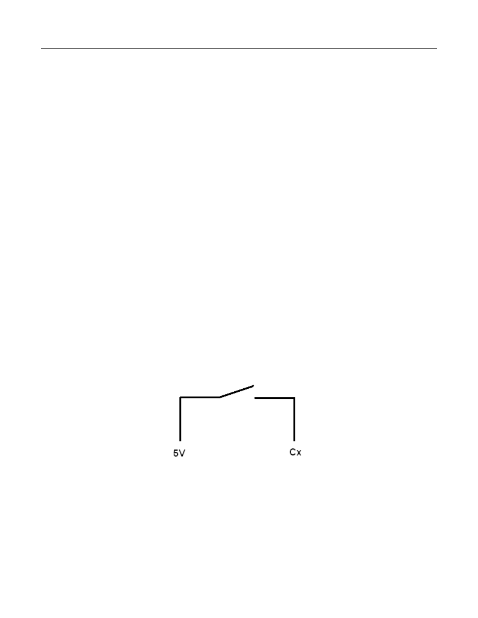
• When digital I/O channels C1 – C8 measure switch-closure inputs, pull-up
resistors may be required. Figure Connecting Switch Closures to Digital I/O
(p. 318)
show how pull-up resistors can be incorporated into a wiring scheme.
• As shown in figure Connecting Switch Closures to Digital I/O
(p. 318),
digital
I/O inputs, with regard to the 6.2-V Zener diode, have an input resistance of
100 kΩ with input voltages < 6.2 Vdc. For input voltages ≥ 6.2 Vdc, the
inputs have an input resistance of only 220 Ω.
FIGURE. Connecting Switch Closures to Digital I/O
Figure 100: Connecting switch closures to digital I/O