Figure 91: deriving ∆v1 – Campbell Scientific CR1000 Measurement and Control System User Manual
Page 299
Section 8. Operation
299
• Effects due to the following are not included in the specification:
o Bridge-resistor errors
o Sensor noise
o Measurement noise
The ratiometric-accuracy specification is applied to a three-wire half-bridge
measurement that uses the BrHalf() instruction as follows:
The relationship defining the BrHalf() instruction is X = V1/Vx, where V1
is the voltage measurement and Vx is the excitation voltage. The
estimated accuracy of X is designated as ∆X, where ∆X = ∆V1/Vx. ∆V1 is
derived using the following method.
The ratiometric-accuracy specification is applied to a four-wire full-bridge
measurement that uses the BrFull() instruction as follows:
The relationship defining the BrFull() instruction is X = 1000*V1/Vx,
where V1 is the voltage measurement and Vx is the excitation voltage.
Result X is expressed as mV/V. Estimated accuracy of X is ∆X, where ∆X
= 1000*∆V1/Vx. ∆V1 is derived using the following method.
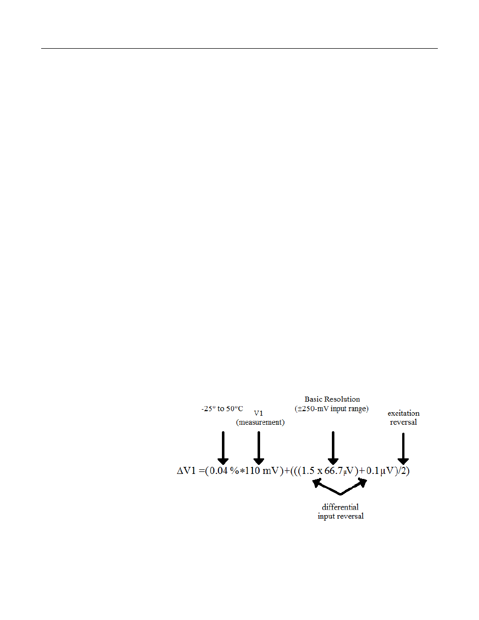
∆V1 is derived using the ratiometric‐accuracy equation. The derivation
is illustrated in this example, which is supported by the assumption that
the measurement is differential with input reversal, datalogger
temperature is between ‐25° to 50°C, analog‐input range is ±250 mV, V1
= 110 mV, and excitation is reversed during the excitation phase of the
measurement. The effect each assumption has on the magnitude of
∆V1 in this example is noted in the following figure.
Figure 91: Deriving ∆V1