7 sdi-12 recording, 8 rs-232 and ttl – Campbell Scientific CR1000 Measurement and Control System User Manual
Page 323
Section 8. Operation
323
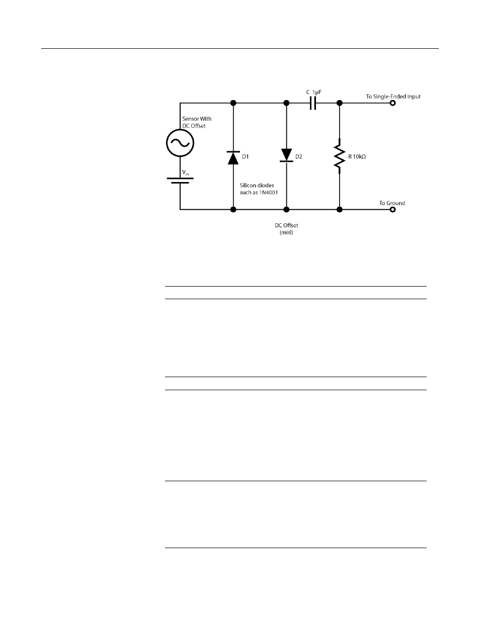
Figure 102: Input conditioning circuit for period averaging
8.1.7 SDI-12 Recording
Read More! SDI-12 Sensor Support
(p. 172)
and Serial Input / Output
(p. 509).
SDI-12 is a communications protocol developed to transmit digital data from
smart sensors to data-acquisition units. It is a simple protocol, requiring only a
single communication wire. Typically, the data-acquisition unit also supplies
power (12 Vdc and ground) to the SDI-12 sensor. The CR1000 is equipped with 4
SDI-12 channels (C1, C3, C5, C7) and an SDI12Recorder() CRBasic instruction.
8.1.8 RS-232 and TTL
Read More! Serial Input / Output Instructions
(p. 509)
and Serial I/O
(p. 200).
The CR1000 can usually receive and record RS-232 and 0 – 5 Vdc logic data
from sensors designed to transmit via these protocols. Data are received through
the CS I/O port with the proper interface (see the appendix CS I/O Serial
Interfaces
(p. 567)
), the RS-232 port, or the digital I/O communication ports (C1 &
C2, C3 & C4, C5 & C6, C7 & C8). If additional serial inputs are required, serial
input expansion modules (see the appendix Serial Input Expansion Modules
) can
be connected to increase the number of serial ports. Serial data are usually
captured as text strings, which are then parsed (split up) as defined in the user
entered program.
Note Digital I/O communication ports (control ports) only transmit 0 – 5 Vdc
logic. However, they read most true RS-232 input signals. When connecting serial
sensors to an Rx control port, the sensor power consumption may increase by a
few milliamps due to voltage clamps. An external resistor may need to be added
in series to the Rx line to limit the current drain, although this is not advisable at
very high baud rates. Figure Circuit to Limit Control Port Input to 5 Volts (p.
324) shows a circuit that limits voltage input on a control port to 5 Vdc.