Digital outputs 1 - 6, Process inputs 1 through 12 – Watlow EZ-ZONE RM Limit Module Rev C User Manual
Page 25
Warning:
ç
Use National Electric (NEC) or other
country-specific standard wiring and
safety practices when wiring and
connecting this controller to a power
source and to electrical sensors or pe-
ripheral devices. Failure to do so may
result in damage to equipment and
property, and/or injury or loss of life.
Note:
Maximum wire size termination and
torque rating:
• 0.0507 to 3.30 mm2 (30 to 12 AWG)
single-wire termination or two 1.31
mm2 (16 AWG)
• 0.8 Nm (7.0 in-lb.) torque
Note:
Adjacent terminals may be labeled
differently, depending on the model
number.
Note:
To prevent damage to the controller,
do not connect wires to unused ter-
minals.
Note:
Maintain electrical isolation between
digital input-outputs, switched dc/open
collector outputs and process outputs
to prevent ground loops.
Watlow EZ-ZONE
®
RML Module
•
22
•
Chapter 2 Install and Wire
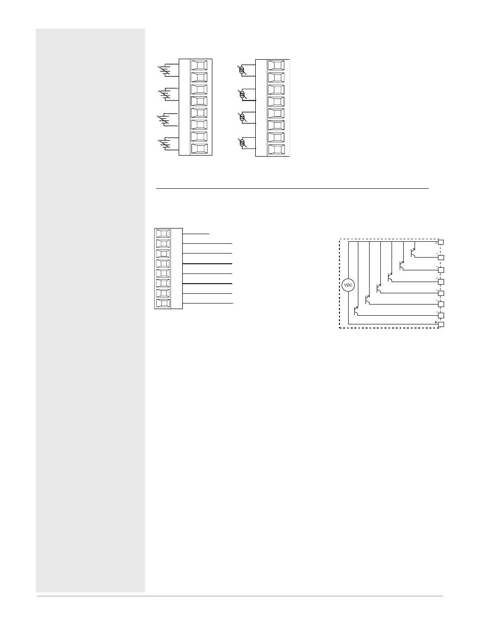
Open Collector/Switched DC
Outputs
Internal Circuitry
Common
open collector/switched dc
B1
D1
D2
D3
D4
D5
D6
Z7
Slot D
Supply
open collector/switched dc
open collector/switched dc
open collector/switched dc
open collector/switched dc
open collector/switched dc
Internal
Suppressor Note:
Switching pilot duty inductive loads (re-
lay coils, solenoids, etc .) with the me-
chanical relay, solid state relay or open
collector output options requires use of
an R .C . suppressor
.
Digital Outputs 1 - 6
RML Part # Digit 7 is C
• Maximum switched voltage is
32VÎ (dc)
• Internal supply provides a
constant power output of
750mW
• Maximum output sink cur-
rent per output is 1.5A (ex-
ternal class 2 or *SELV sup-
ply required)
• Total sink current for all out-
puts not to exceed 8A
• Do not connect outputs in
parallel
- Slot D DO 1 - 6
RMLx-xx(C)x-xxxx
*Saftey Extra Low Voltage
B_
D_
Z_
D_
D_
D_
D_
D_
Process Inputs 1 through 12
RML Part # Digit 5, 6, 7 is 5
-
+
-
+
-
+
-
+
S_
R_
S_
R_
S_
R_
S_
R_
Slot A, B, D
-
+
-
+
-
+
-
+
S_
R_
S_
R_
S_
R_
S_
R_
Slot A, B, D
• 0 to 20 mA @ 100 Ω input impedance
• 0 to 10V
Î
(dc) @ 20 kΩ input imped-
ance
• 0 to 50 mV
Î
(dc) @ 20 MΩ input im-
pedance
• scalable
Slot 1:
RMLx-(5)xxx-xxxx
(Inputs 1 to 4)
Slot 2:
RMLx-x(5)xx-xxxx
(Inputs 5 to 8)
Slot 3:
RMLx-xx(5)x-xxxx
(Inputs 9 to 12)