IAI America RCM-GW-PR User Manual
Page 87
81
PfofiBus Gateway
(11) Command position number (PC1 to PC512) PLC output signal
A command position number is read as a binary code.
The number of command positions varies as follows according to the operation mode:
• Position number specification mode
PC1 to PC32
64 points
• Command specification mode, positioner operation
PC1 to PC256
512 points
• Command specification mode, simple direct operation
PC1 to PC32768
The controller unit reads the PC signal as a binary command position number at the “0” (OFF)
Æ “1”
(ON) edge of the CSTR signal.
(12) Completed position number (PM1 to PM256) PLC input signal
These signals are effective in simple direct operation in the position number specification mode and
command specification mode. A completed position number is output as a binary code.
When the power is turned on or the actuator is moving, all PM signals from 1 to 256 turn “0” (OFF).
When the servo turns off or an emergency stop is actuated, all signals turn "0" (OFF). However, the
applicable signal will turn “1” (ON)” again when the servo subsequently turns on, if the actuator is
inside the positioning band (INP) relative to the target position. If the actuator has exceeded the
positioning band (INP), the signals will remain “0” (OFF).
The applicable PM signal will also turn “1” (ON) when the push-motion operation has completed or
the actuator has missed the load.
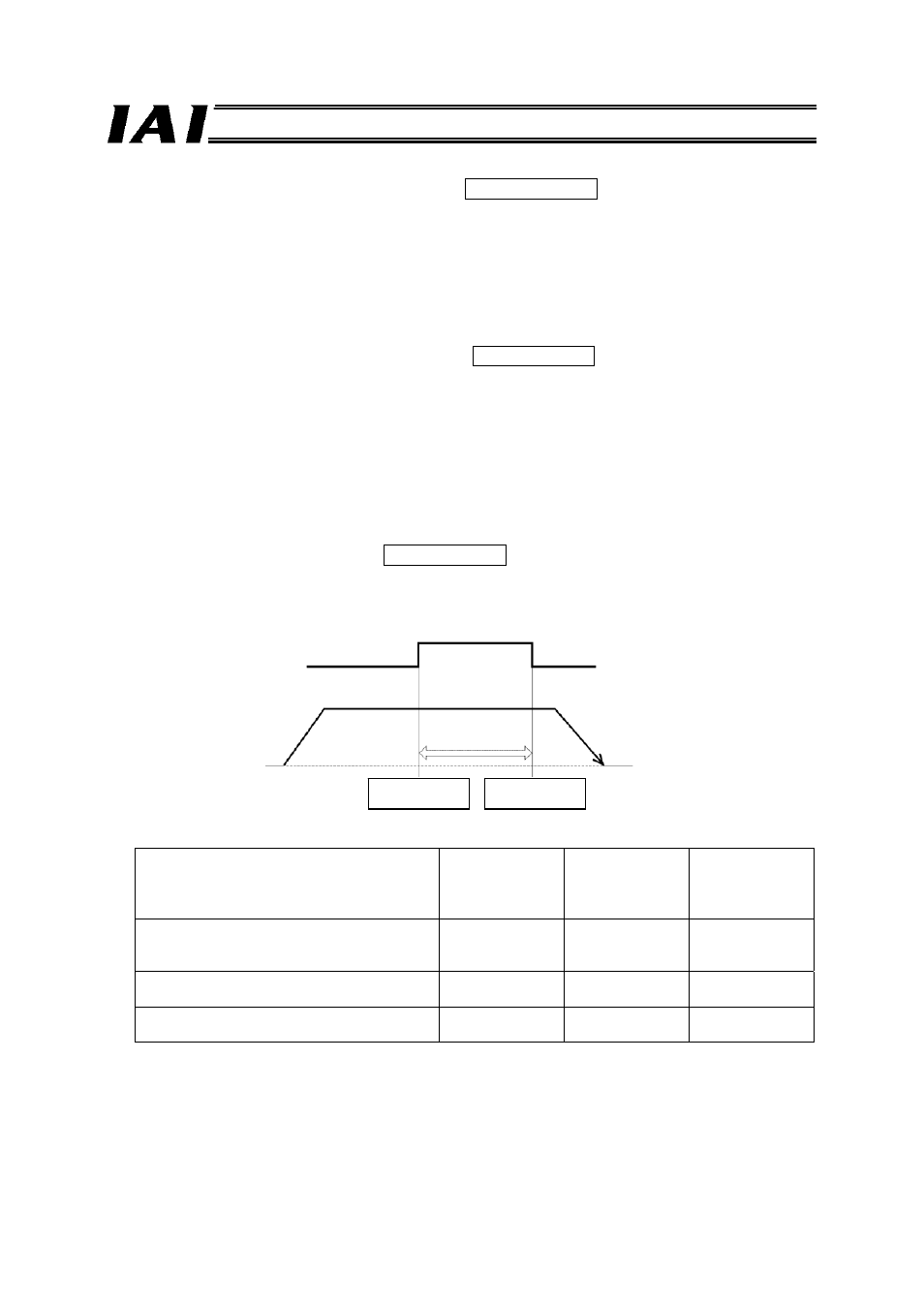
(13) Zone (PZONE, ZONE1, ZONE2) PLC input signal
Each of these signals turns “1” (ON) when the current actuator position is inside the specified zone.
*1
A desired zone can be set in the position table or using user parameters.
Setting Zone
signal
Position number
specification
mode
Command
specification
mode, positioner
operation
Individual zone boundary fields in position
table
Position zone
output
PZONE
X
{ *2
User parameter “Zone boundary 1”
(Parameter No. 1 = + side, No. 2 = - side)
Zone output 1
ZONE1
{
{ *3
User parameter “Zone boundary 2”
(Parameter No. 23 = + side, No. 24 = - side)
Zone output 2
ZONE2
{
X
*1 This signal becomes effective when the home return has completed. As long as the home return
has completed once, this signal remains effective even when the servo is off.
*2 PIO pattern 3 is not supported.
*3 PIO patterns 1 to 3 are not supported.
Zone signal
Actuator operation
Home
Zone setting-
Zone setting+
+ direction