3 assignment for each axis – IAI America RCM-GW-PR User Manual
Page 66
60
PfofiBus Gateway
5.3.3 Assignment for Each
Axis
The I/O signals of each axis vary in terms of the size and content of each applicable area depending
on whether the axis is a positioner operation axis or simple direct operation axis.
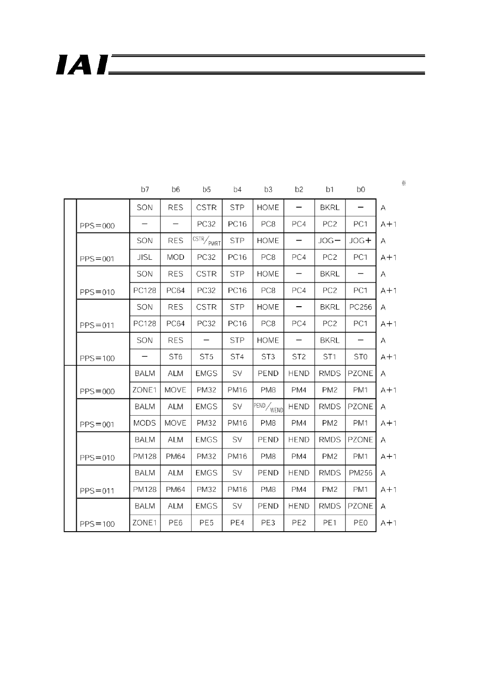
(1) Control/status signals for positioner operation axis
Each axis consists of two PLC output (control signal) bytes and two PLC input (status signal) bytes,
as shown below. Five patterns are available depending on the PIO pattern set by the gateway control
signal PPS.
* Byte address A: Gateway head address + 18 + 2n
n: Axis number assigned to a positioner operation axis (0 or greater)
Byte address
PLC output
PLC inpu
t
Pattern 0
(standard mode)
Pattern 1
(teaching mode)
Pattern 2
(256 positioning
points)
Pattern 3
(512 positioning
points)
Pattern 4
(solenoid mode
1)
Pattern 0
(standard mode)
Pattern 1
(teaching mode)
Pattern 2
(256 positioning
points)
Pattern 3
(512 positioning
points)
Pattern 4
(solenoid mode
1)