IAI America RCM-GW-PR User Manual
Page 120
114
PfofiBus Gateway
Appendix 1. Sample Programs for S7-300
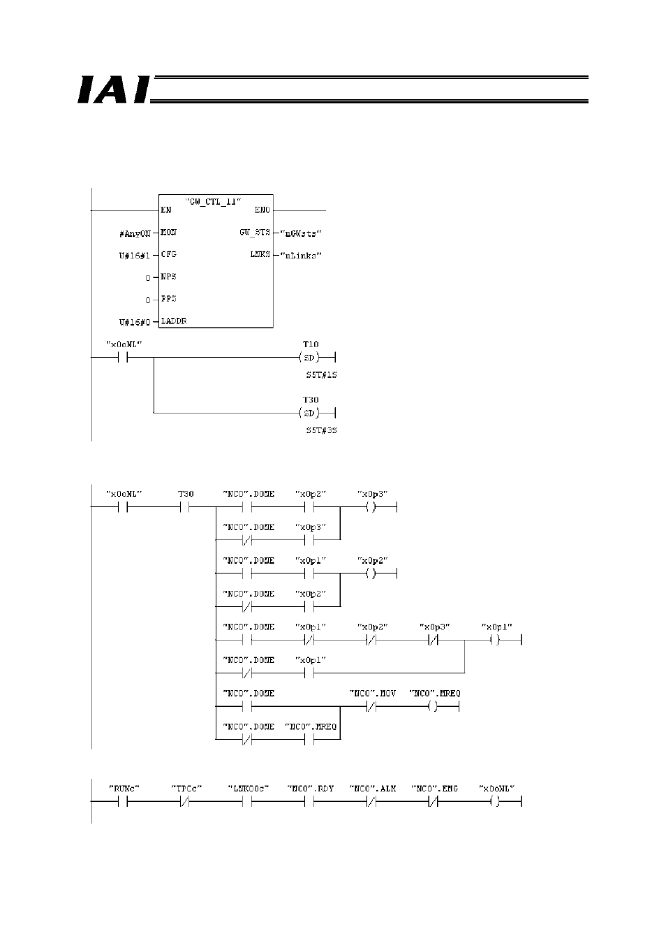
Example of Using RC_NVC_11 and GW_CTL_11
#AnyON is always ON.
GW/controller communication starts (MON).
Axis 0 is configured (W#16#1).
The Gateway I/O head addresses are “0.”
Servo on delay timer
Homing delay timer
The next target position is controlled based on the movement
completion pulse (NC0.DONE) output by a FB.
The target position changes in the sequence of x0p1
→ x0p2 →
x0p3
→ x0p1, …, every time the NC0.DONE pulse is input.
Online status is checked from the STS_W, LNK_W and RC_NVC_11 (instance name: NC0) outputs.
See also other documents in the category IAI America Hardware:
- ERC2 (138 pages)
- ERC2 (188 pages)
- ERC3 (438 pages)
- ERC (153 pages)
- RCA-E (53 pages)
- RCA-P (42 pages)
- RCB-101-MW (38 pages)
- RCP2-C (178 pages)
- RCS-E (102 pages)
- RCA-A4R (72 pages)
- RCA-RA3C (114 pages)
- RCA-SRA4R (56 pages)
- RCA2-RA2AC (100 pages)
- RCA2-SA2AC (92 pages)
- RCA2-TA4C (134 pages)
- RCD-RA1D (40 pages)
- RCP2-BA6 (72 pages)
- RCP2-GRSS (130 pages)
- RCP2-HS8C (126 pages)
- RCP2-RA2C (120 pages)
- RCP2-RTBS (80 pages)
- RCP2W-SA16C (46 pages)
- RCP3-RA2AC (60 pages)
- RCP4-RA5C (82 pages)
- RCP4-SA5C (94 pages)
- RCP4W (96 pages)
- RCS2-F5D (142 pages)
- RCS2-GR8 (46 pages)
- RCS2-RN5N (80 pages)
- RCS2-RT6 (60 pages)
- RCS2-SA4C (258 pages)
- RCS2-TCA5N (62 pages)
- RCL-SA1L (66 pages)
- RCL-RA1L (56 pages)
- RCLE-GR5L (46 pages)
- IK Series (16 pages)
- FS (84 pages)
- IF (76 pages)
- ISB (114 pages)
- ISDA (126 pages)
- ISDB (116 pages)
- ISPWA (90 pages)
- ICS(P)A (16 pages)
- NS (78 pages)
- RS (46 pages)