IAI America RCM-GW-PR User Manual
Page 61
55
PfofiBus Gateway
5.3.1 Overall
Address Configuration
Input/output Gateway control signals consist of four bytes each. Only in this mode, PPS0 to PPS2
and NPS0 to NPS4 of control signal 0 are used to set the pattern and number of position-number
specification axes. The subsequent 14 bytes constitute the command input/output area, and a total of
18 bytes each for input and output, including the Gateway control signals and command area,
constitute the fixed area.
The control area is assigned after the fixed area for each axis. Address assignment is performed from
position-number specification axes first, followed by simple direct mode axes.
Assign the signals so that no gaps remain between the areas of adjacent axes.
The total I/O area size of the Gateway varies in accordance with the setting of the mode setting
switch SW1, as shown in the table below.
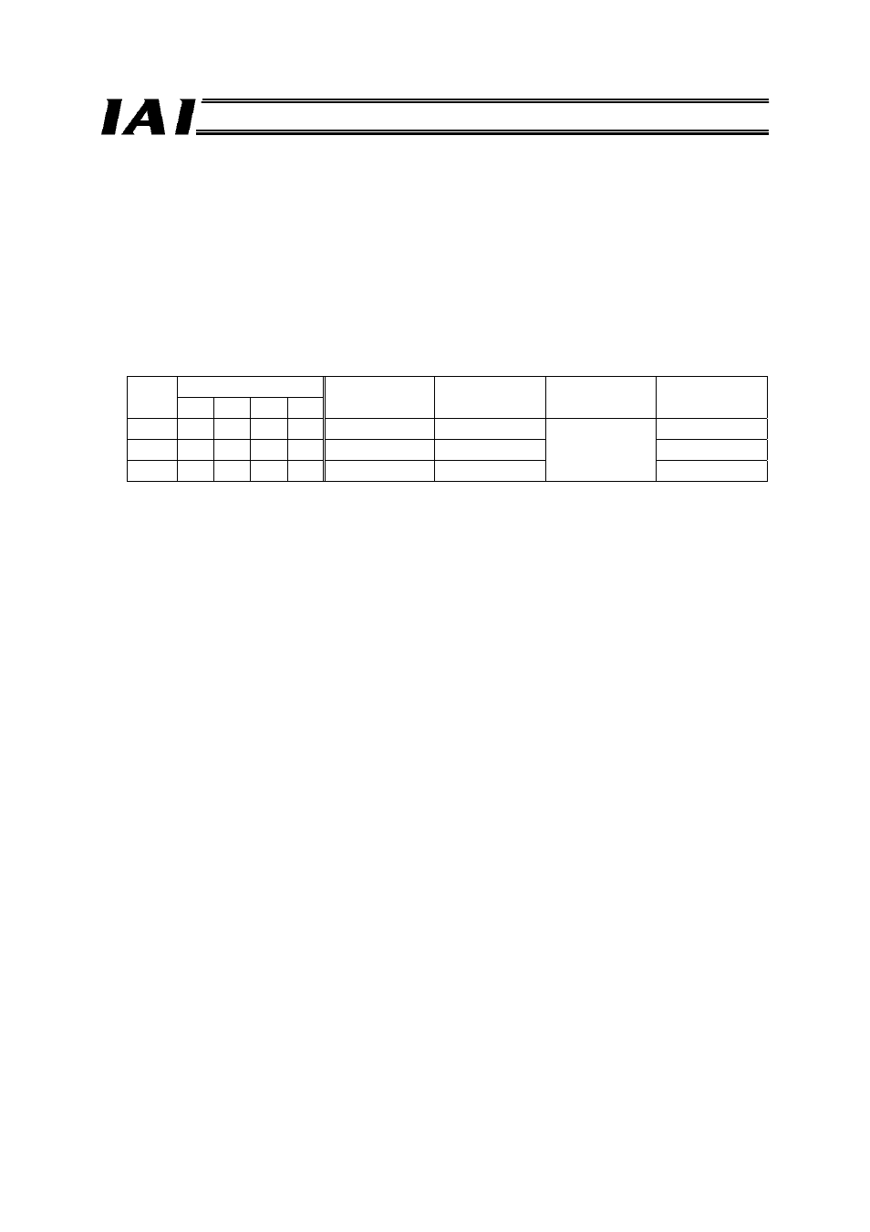
Mode
No.
SW1
- Total
I/O
area
Fixed
area
Axis control
area
4 3 2 1
7 X
X
X
{
Large mode
160 bytes each
18 bytes each
142 bytes each
8 X
{
X
{
Middle mode
128 bytes each
110 bytes each
9
{
X X {
Small mode
64 bytes each
46 bytes each
Up to 16 axes, including positioner operation axes and simple direct operation axes, can be assigned
within the range specified in the table above.
The control signals of each axis occupy two input bytes and two output bytes in the case of a
positioner operation axis, or six PLC input bytes and eight PLC output bytes in the case of a simple
direct operation axis.
An example of assigning four positioner operation axes and four simple direct operation axes to be
operated in the Small mode is shown on the following page.