3 name and function of each part – IAI America RCM-GW-PR User Manual
Page 16
10
PfofiBus Gateway
2.3 Name and Function of Each Part
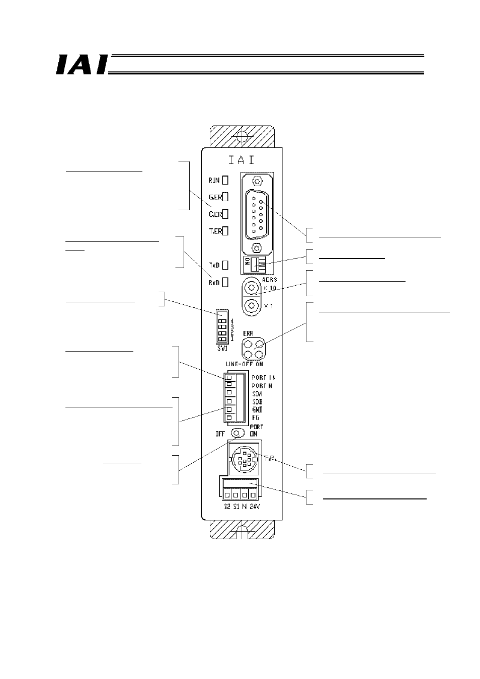
[1] Gateway Status LEDs
RUN: Normal
G.ER: Error
C.ER: ProfiBus controller error
T.ER: SIO link error
[2] SIO communication status
LEDs
TxD: Sending data
RxD: Receiving data
[3] Mode setting switch
[4] Port switching input
PORT IN: Port switching input
PORT N: N
[5] Controller communication lines
SDA: Communication line
SDB: Communication line
GND: Ground
FG: Frame
ground
[10] Port switch
ON: Port
ON
OFF: Port OFF
[6] ProfiBus communication connector
[7] Termination switch
[8] Address setting switches
X10 and X1 (decimal, 2 digits)
[9] ProfiBus communication Status LEDs
ON: Online
OFF: Offline
ERR: Error
[11] Teaching pendant/PC connector
[12] Power-supply input connector
- ERC2 (138 pages)
- ERC2 (188 pages)
- ERC3 (438 pages)
- ERC (153 pages)
- RCA-E (53 pages)
- RCA-P (42 pages)
- RCB-101-MW (38 pages)
- RCP2-C (178 pages)
- RCS-E (102 pages)
- RCA-A4R (72 pages)
- RCA-RA3C (114 pages)
- RCA-SRA4R (56 pages)
- RCA2-RA2AC (100 pages)
- RCA2-SA2AC (92 pages)
- RCA2-TA4C (134 pages)
- RCD-RA1D (40 pages)
- RCP2-BA6 (72 pages)
- RCP2-GRSS (130 pages)
- RCP2-HS8C (126 pages)
- RCP2-RA2C (120 pages)
- RCP2-RTBS (80 pages)
- RCP2W-SA16C (46 pages)
- RCP3-RA2AC (60 pages)
- RCP4-RA5C (82 pages)
- RCP4-SA5C (94 pages)
- RCP4W (96 pages)
- RCS2-F5D (142 pages)
- RCS2-GR8 (46 pages)
- RCS2-RN5N (80 pages)
- RCS2-RT6 (60 pages)
- RCS2-SA4C (258 pages)
- RCS2-TCA5N (62 pages)
- RCL-SA1L (66 pages)
- RCL-RA1L (56 pages)
- RCLE-GR5L (46 pages)
- IK Series (16 pages)
- FS (84 pages)
- IF (76 pages)
- ISB (114 pages)
- ISDA (126 pages)
- ISDB (116 pages)
- ISPWA (90 pages)
- NS (78 pages)
- ICS(P)A (16 pages)
- RS (46 pages)