IAI America RCM-GW-PR User Manual
Page 26
20
PfofiBus Gateway
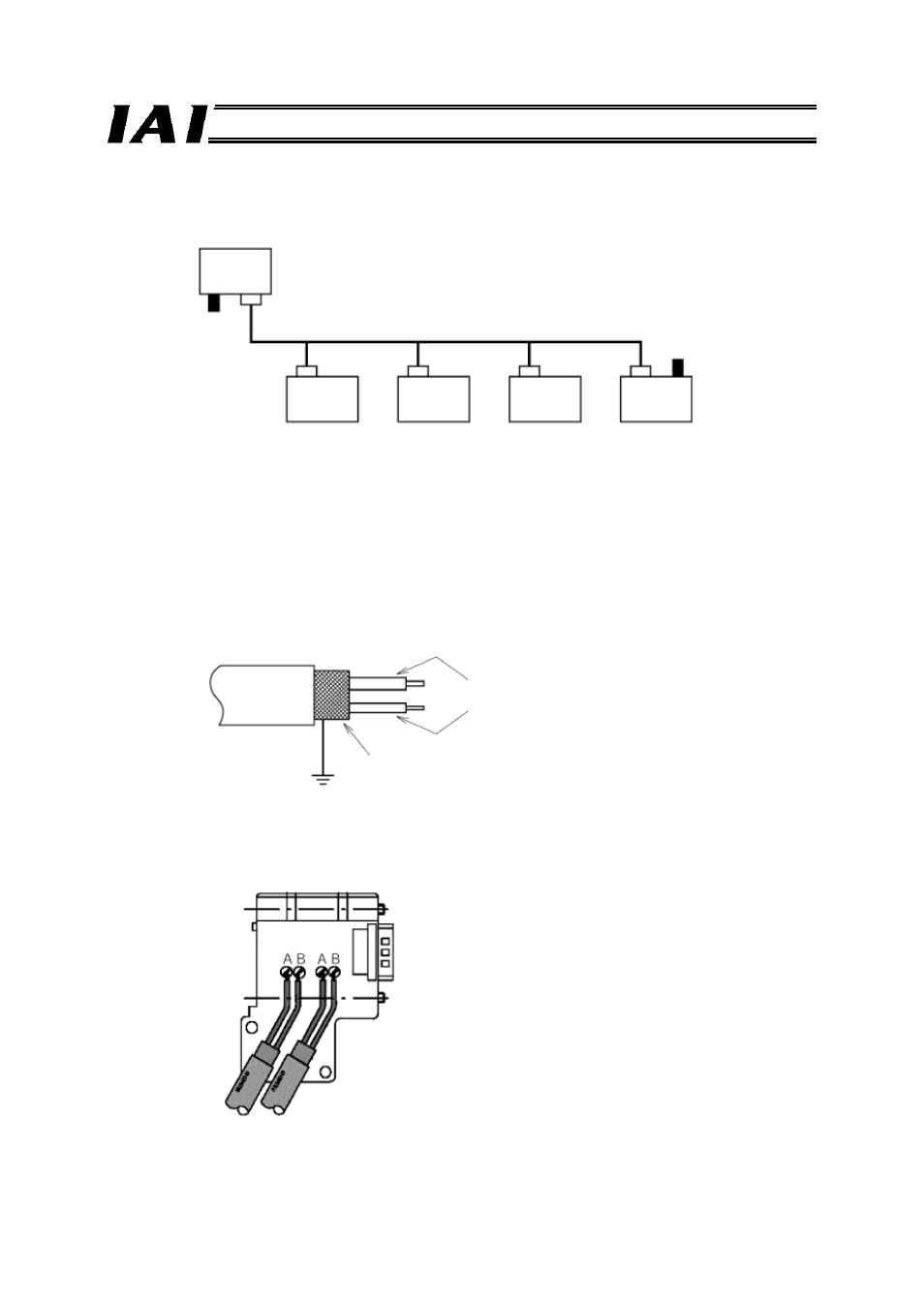
The ProfiBus network is wired as shown below.
For details on ProfiBus-DP, check the operation manual for the master (PLC) or website of the
Japanese PROFIBUS Organization.
[1] A device connected to a network and assigned an address is called a “node.” A node may be a
master or slave. Up to 32 nodes can be connected to one segment.
[2] It is recommended that the master be connected to one end of the network. Normally the master has
node address 2, while each slave has node address 3 to 32.
Node address 0 is reserved for a monitoring or diagnostic device, while node address 1 is reserved
for a monitoring device.
[3] One segment of the network must have a terminal resistor connected to both ends.
[4] For each ProfiBus cable, use the ProfiBus-DP type A cable specified by the EN 50170 standard. This
cable is a 2-core twisted pair cable with shield.
[5] All network connectors should be the D-sub, 9-pin connector specified by the EN 50170 standard.
The network bus connector can be of the screw type shown below or the quick connection type
where the wires are inserted into provided holes.
If the connector has a terminal resistor, turn the
terminal resistor switch ON only for the terminal slave,
and turn the switch OFF for all other slaves.
Master
(Node address 2)
Slave
Slave
Slave
Slave
Terminal
resistor
Terminal
resistor
(Node address 3) (Node address 4) (Node address 5) (Node address 6)
Cable
Red: Line B (positive side)
Green: Line A (negative side)
Shield