IAI America RCM-GW-PR User Manual
Page 11
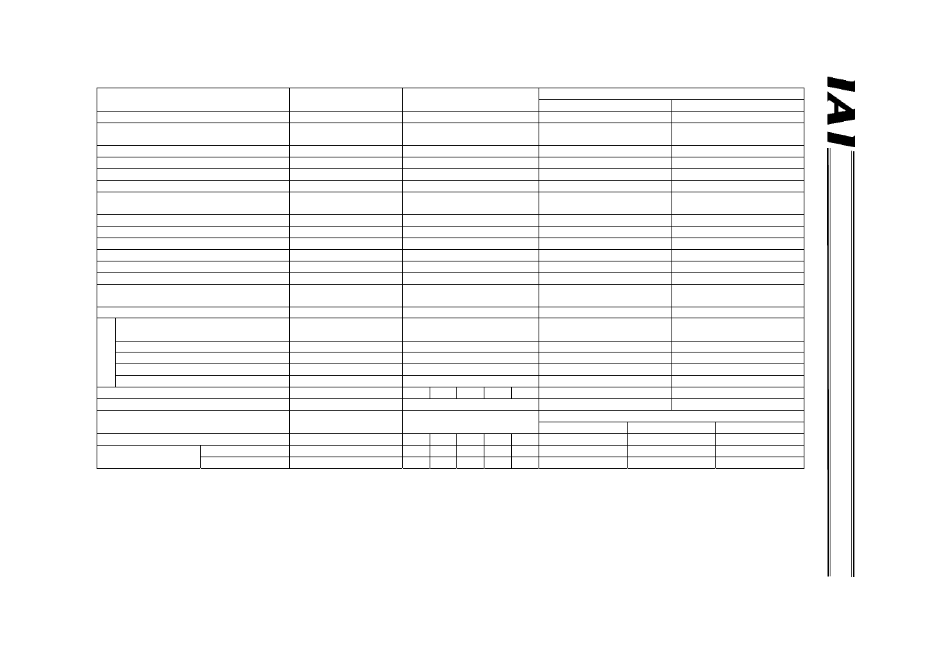
PROF
IBUS Gate
w
a
y
Key function
Position number
specification mode
Direct numerical specification
mode
Command specification mode
Positioner operation
Simple direct operation
Operation by position data specification
X (P table specification)
{
{ (P table rewriting)
{
Direct specification of speed and
acceleration/deceleration
X (P table specification)
{
{ (P table rewriting)
X (P table specification)
Direct specification of positioning band
X (P table specification)
{
{ (P table rewriting)
X (P table specification)
Push-motion operation
{ (P table specification)
{
{ (P table specification)
{ (P table specification)
Operation by position number specification
{
X
{
X
Position table enabling
{
X
{
{
Maximum number of storable position
numbers
64 - 512 512
Reading of completed position number
{
X
{
X
Selection of controller PIO pattern
X
X
{ *2
X
Zone (parameter)
{ (2)
X
{ *3
X
Position zone (P table)
X
X
{ *4
X
Reading of various status signals
{
{
{
{
Speed change during movement
{
{
{
{
Operation at different acceleration and
deceleration
{
{
{
{ (P table specification)
Monitoring of current position *5
X
{
X
{
C
o
m
m
a
nd
Sending/receiving of
commands/responses
X X {
{
Reading/writing of P table data
X
X
{
X
Reading of current position *6
X
X
{
{
Reading of alarm code
X
X
{
{
Broadcasting X
X
{
X
Number of connectable axes
16
4
6
8
10
16
16
16
Maximum specifiable value of position data
P table specification
9999.99 mm
9999.99 mm
9999.99 mm
Large mode
Middle mode
Small mode
Mode setting SW1
2
0
4
8
13
12
1
5
9
Gateway I/O bytes
Input
48
28 40 52 64 100
160
128
64
Output 48
52
76
100
124
196
160
128
64
*1 P table: Position table
*2 PIO patterns 0 to 4 can be selected.
*3 PIO patterns 1 to 3 are not supported.
*4 PIO pattern 3 is not supported.
*5 In the current position monitoring function, the current position data is assigned to a gateway output signal.
Accordingly, the current position can be read directly from the PLC.
*6 Reading the current position means reading the current position data indirectly with the PLC issuing a read command to the gateway.