Caution – IAI America RCM-GW-PR User Manual
Page 35
29
PfofiBus Gateway
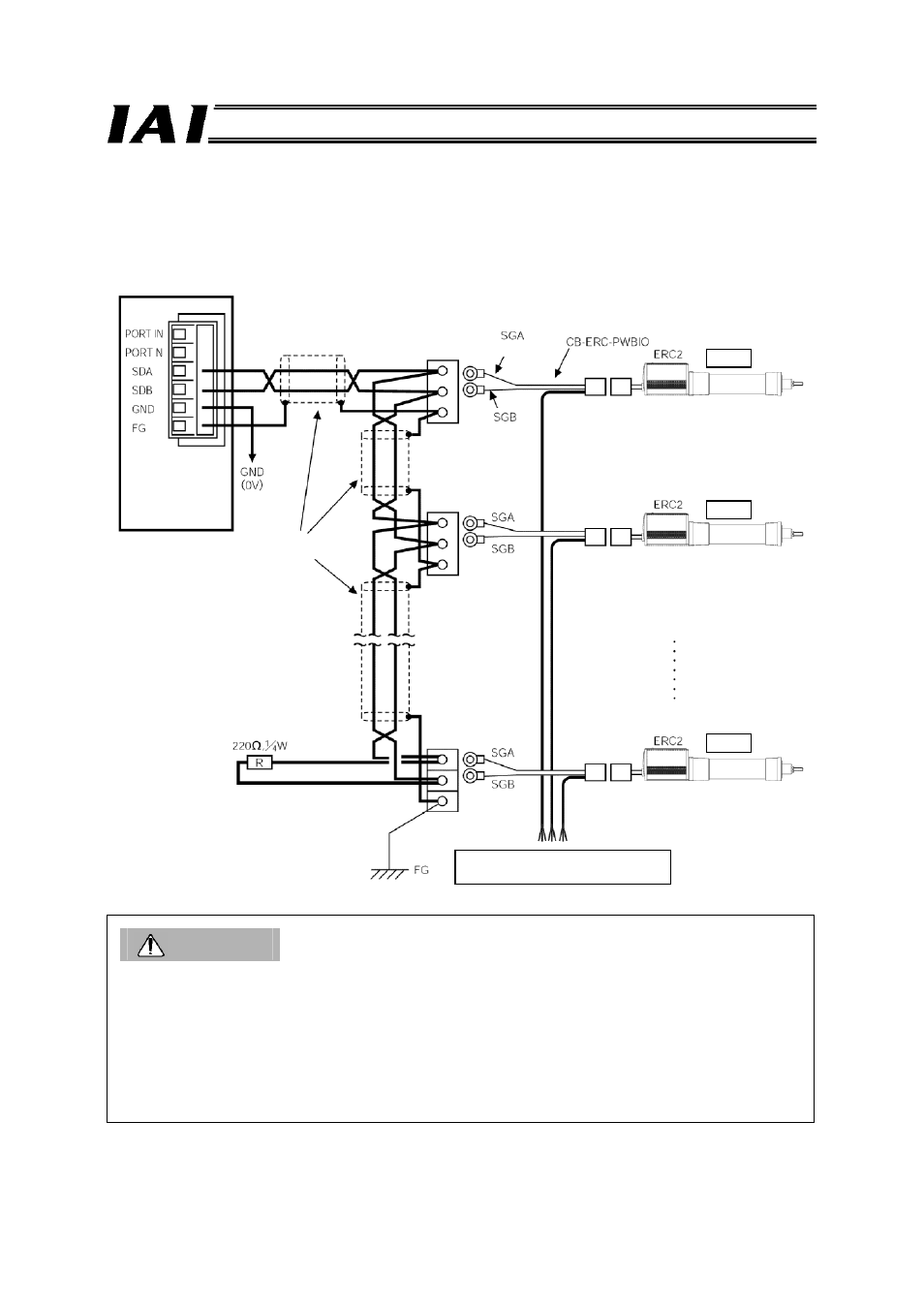
(4) SIO communication connection for ERC2-NP/PN
Use relay terminal blocks to connect the cables as shown below.
Caution
(1) When the total communication cable length is 10 m or longer, communication may not be
established properly and a communication error may occur. In this case, connect a terminal
resistor to the last axis.
(2) If the actuators have different power supplies, use a common line for 0 [V].
(3) Use a common line for 0 [V] for the power supply of the gateway unit and control power supply of
the ERC2.
(4) Connect the shield wire to the FG for each axis.
(5) If the total link cable length exceeds 30 m, use wires with a size of 22AWG or larger.
PIO & 24-VDC control power, motor
power, brake signal, ground, shield
Terminal resistor
Gateway unit
Axis 1
Axis 2
Axis 16
Relay terminal
block
Orange
(red 1)
PIO type power-supply & I/O cable
Orange
(black 1)
Pair shield cable
(fabricated by the
customer)