IAI America RCM-GW-PR User Manual
Page 12
6
PfofiBus Gateway
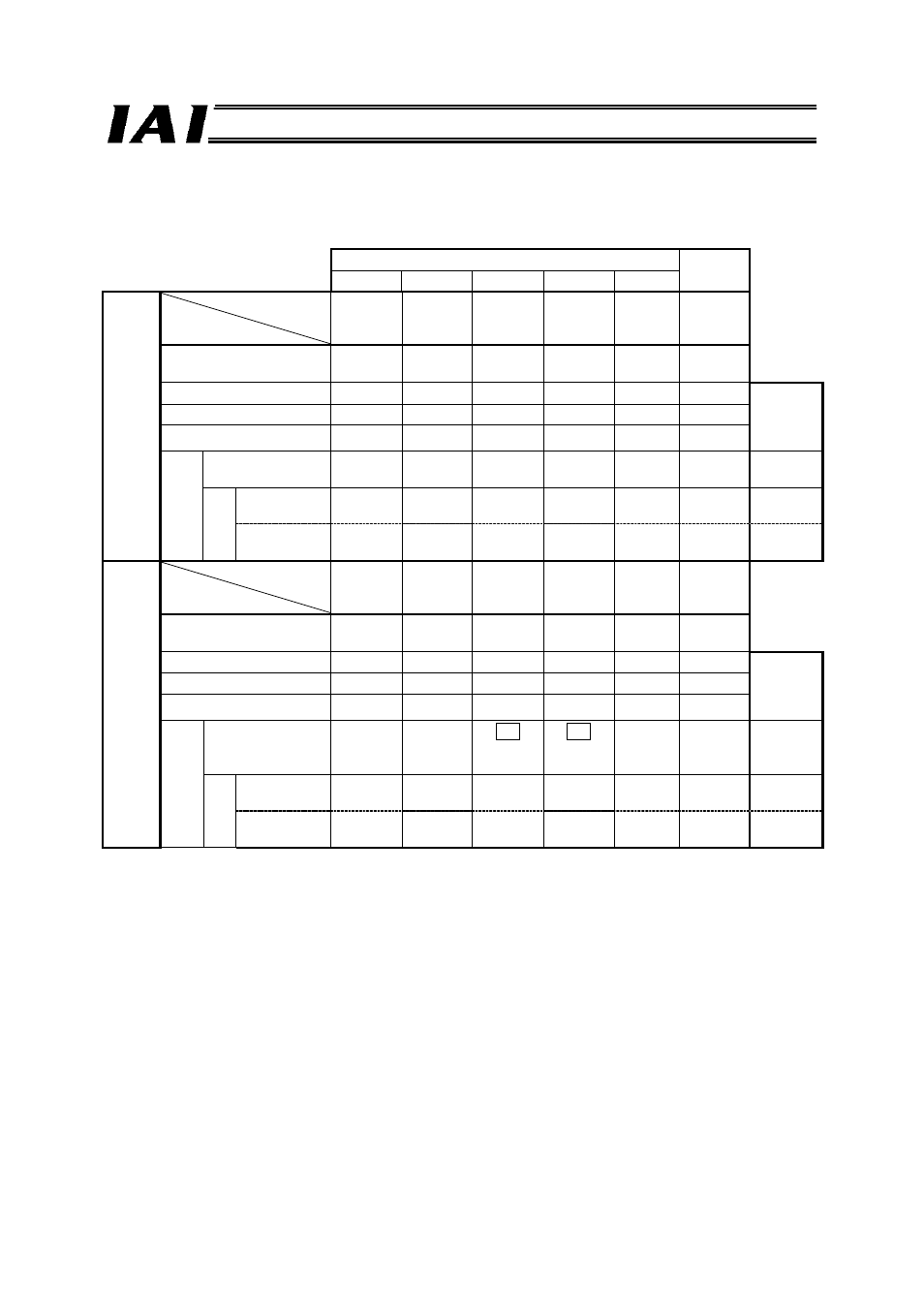
Next, the relationship of the number of positions supported by each controller under each PIO pattern, and
the maximum number of positions that can be stored in the gateway unit, is explained. Take note that the
number of positions may become subject to restrictions.
PIO pattern (Parameter No. 25)
SE
0 1 2 3 4
ERC2
Operation type
Standard
Solenoid
type
Zone
signal
type
Position
zone type
-
Dedicated
SIO
operation
Number of positioning
points
8 3 16
16 - 64
Home return signal
{
X X X - {
Maximum
number of
gateway
positions
Zone signal
{
X
{
X - {
P zone signal
X
X
X
{
-
{
Gateway con
tr
o
l
Position number
specification mode
8
*1
X
16
*1
16
*1
- 64 64
Command
specif
ica
ti
o
n
Positioner
operation
*1 *3
8 (0)
X
*1 *3
16 (2)
*1 *3
16 (3)
-
*3
64 (0)
512
Simple direct
operation
- X - - - - 512
PCON
ACON
SCON
Operation type
Positioning
mode
Teaching
mode
256-point
mode
512-point
mode
Solenoid
mode 1
Dedicated
SIO
operation
Number of positioning
points
64 64 256
512 7 64
Home return signal
{
{
{
{
{
{
Maximum
number of
gateway
positions
Zone signal
{
X X X {
{
P zone signal
{
{
{
X
{
{
Ga
te
way control
Position number
specification mode
64 64
256
↓
64 *2
512
↓
64 *2
7 64 64
Command
Command
specif
ica
tion
if
i
ti
Positioner
operation
*3
64 (0)
*3
64 (1)
*3
256 (2)
*3
512 (3)
*3
7 (4)
*3
64 (0)
512
Simple direct
operation
- - - - - -
512
*1 In the operation mode based on position number specification, the number of positions is limited
according to the selected PIO pattern (parameter No. 25). (The gateway can handle more positions.)
*2 Since the gateway can handle 64 positions, the number of controller positions is limited.
*3 In the case of a positioner operation axes operating in the command specification mode, the PIO
pattern selection parameter of the controller must correspond to the I/O pattern set by gateway
control signals PPS0 to PPS2. The numbers of positions shown in parentheses ( ) indicate values set
by PPS0 to PPS2.