IAI America RCM-GW-PR User Manual
Page 19
13
PfofiBus Gateway
[6] ProfiBus
communication
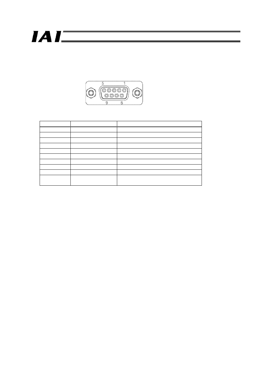
connector
This connector is used to connect the ProfiBus communication lines.
D-sub, 9-pin connector (female)
ProfiBus communication connector
Pin No.
Signal name
Description
1 NC
Not
connected
2 NC
Not
connected
3
B-Line
Communication line B (RS485)
4
RTS
Request to send
5
GND
Signal ground (insulated)
6 +5V
+5-V
output
(insulated)
7 NC
Not
connected
8
A-Line
Communication line A (RS485)
9 NC
Not
connected
Housing Shield
Cable shield
Connected to the frame.
The mating connector (cable end) is not supplied.
[7] Termination
switch
A terminal resistor must be provided at the end of the ProfiBus trunk line to prevent bus reflection.
Set the termination switch to the ON position when the ProfiBus Gateway is the terminal module.
However, the switch should be set to the OFF position if an external termination connector is used.
Set the switch to the OFF position if the Gateway is not the terminal module.
[8] Address setting switches
The two rotary switches are used to set a decimal node address in a range of 1 to 99.
X10: Set the 10’s digit of the two-digit decimal address.
X1:
Set the 1’s digit of the two-digit decimal address.
This switch is normally set to 2 for the master unit, and 3 or greater for the slave.