6 communication signal details, 1 overview of communication signal timings – IAI America RCM-GW-PR User Manual
Page 81
75
PfofiBus Gateway
6 Communication
Signal
Details
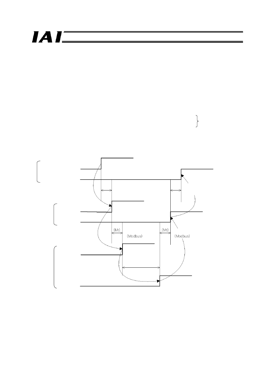
6.1 Overview of Communication Signal Timings
When a given control signal is turned ON to operate the ROBO Cylinder using the sequence program in
the PLC, the maximum response time before a response (status) signal will be received is expressed by
the formula below:
Maximum response time (msec) = Yt + Xt + 2 x Mt + Command processing time (operation time, etc.)
Mt = 10 (msec) x (n+1): SIO link (Modbus) cycle time
n: Number of controlled axes
Yt: Master
→ remote I/O station transmission delay
Xt: Remote I/O
→ master station transmission delay
For the master
→ remote I/O station transmission delay (Yt) and remote I/O → master station
transmission delay (Xt), refer to the operation manuals for your ProfiBus master unit and PLC.
(Note) If a communication error occurs due to a problem along the transmission path, etc.,
a communication retry or retries (up to three times) may occur, in which case the SIO link cycle
time (Mt) will be extended.
ProfiBus
transmission delay
PLC sequence program
Control signal
Status signal
Master
→ remote I/O station
transmission delay (Yt)
Remote I/O
→ master station
transmission delay (Xt)
Gateway
Control signal
Status signal
Controller
Control signal
Status signal
SIO link cycle time
SIO link cycle time
Response
processing time