Caution, 4 command area – IAI America RCM-GW-PR User Manual
Page 71
65
PfofiBus Gateway
5.3.4 Command
Area
In the command specification mode, command areas are provided to let you use the various
commands explained below to read/write the position table, among others.
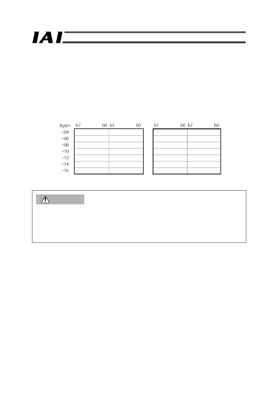
(1) Address configuration
The request command area and response command area consist of 14 bytes each in the range of
(Byte+ 04) to (Byte+ 17).
Caution
If a command code is not synchronized with related data, the command does not function properly.
With Siemens’s S7 Series PLC, synchronicity (consistency) of ProfiBus I/Os is normally guaranteed
only in units of bytes and words. To handle data spanning multiple words synchronously, an applicable
item must be set to ensure data consistency in the STEP 7’s HW Config screen (refer to7.4 (5),
“Setting for I/O data consistency) and the SFC14 and SFC15 must be used (used in the command
function blocks explained in 8).
*1 Byte+ indicates a relative byte address from the initial byte address of the gateway.
*2 Data 4 (RSV) and data 5 (RSV) are not currently used.
*3 If a command error occurs, the most significant bit (b7) of the upper byte of the response command
will turn ON and the applicable error code specified in (4) will be set in response data 1.
Output from PLC
⇒ Gateway Unit
⇒ Input to each axis
Output from each axis
⇒ Gateway Unit
⇒ Input to PLC
Upper byte
Lower byte
Upper byte
Lower byte
Request command
Data 0
Response command
Data 1
Data 2
Data 3
Data 4 (RSV)*2
Data 5 (RSV)*2
Data 0
Data 1*3
(Error code)
Data 2
Data 3
Data 4
(RSV)*2
Data 5
(RSV)*2