IAI America RCM-GW-PR User Manual
Page 17
11
PfofiBus Gateway
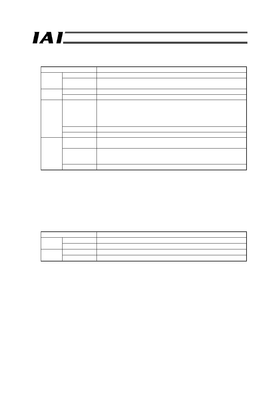
[1] Gateway status LEDs
Indicated status
Description
RUN
Steady green The Gateway CPU is operating.
Unlit
CPU operation is stopped. If this LED does not come on after turning on
the power, the Gateway is experiencing a CPU error.
G.ER
Steady red
The Gateway is experiencing a CPU error or major shutdown failure.
Unlit Normal
state.
C.ER
Steady red
The ProfiBus module is experiencing an error or the Gateway CPU
cannot recognize the ProfiBus connection. (Check the ProfiBus
communication status in [9].)
Even if this LED is lit, the teaching pendant or PC software can still be
connected as long as the RUN LED is lit.
Blinking red
While the port is ON, this LED blinks at 1-second intervals.
Unlit Normal
state.
T.ER
Steady red
All axes generated a communication error based on SIO communication
between the ProfiBus gateway and controller.
Blinking red
At least one axis generated a communication error based on SIO
communication between the ProfiBus gateway and controller. (No
response, overrun, flaming error or CRC
(*)
error)
Unlit Normal
state.
* CRC: Cyclic Redundancy Check
A data error detection method commonly used in synchronous transmission.
[2] SIO communication status LEDs
These LEDs are used to check the communication status between the ProfiBus Gateway and the
controller.
Each LED blinks when the host PLC and controller are not communicating via the ProfiBus Gateway,
or when the controller is communicating with the teaching pendant or PC software connected via the
ProfiBus Gateway.
Indicated status
Description
TxD Blinking
green
Sending data (ProfiBus Gateway
→ Controller)
Unlit
Not sending data (ProfiBus Gateway
→ Controller)
RxD Blinking
green
Receiving data (Controller
→ ProfiBus Gateway)
Unlit
Not receiving data (Controller
→ ProfiBus Gateway)