IAI America RCM-GW-PR User Manual
Page 84
78
PfofiBus Gateway
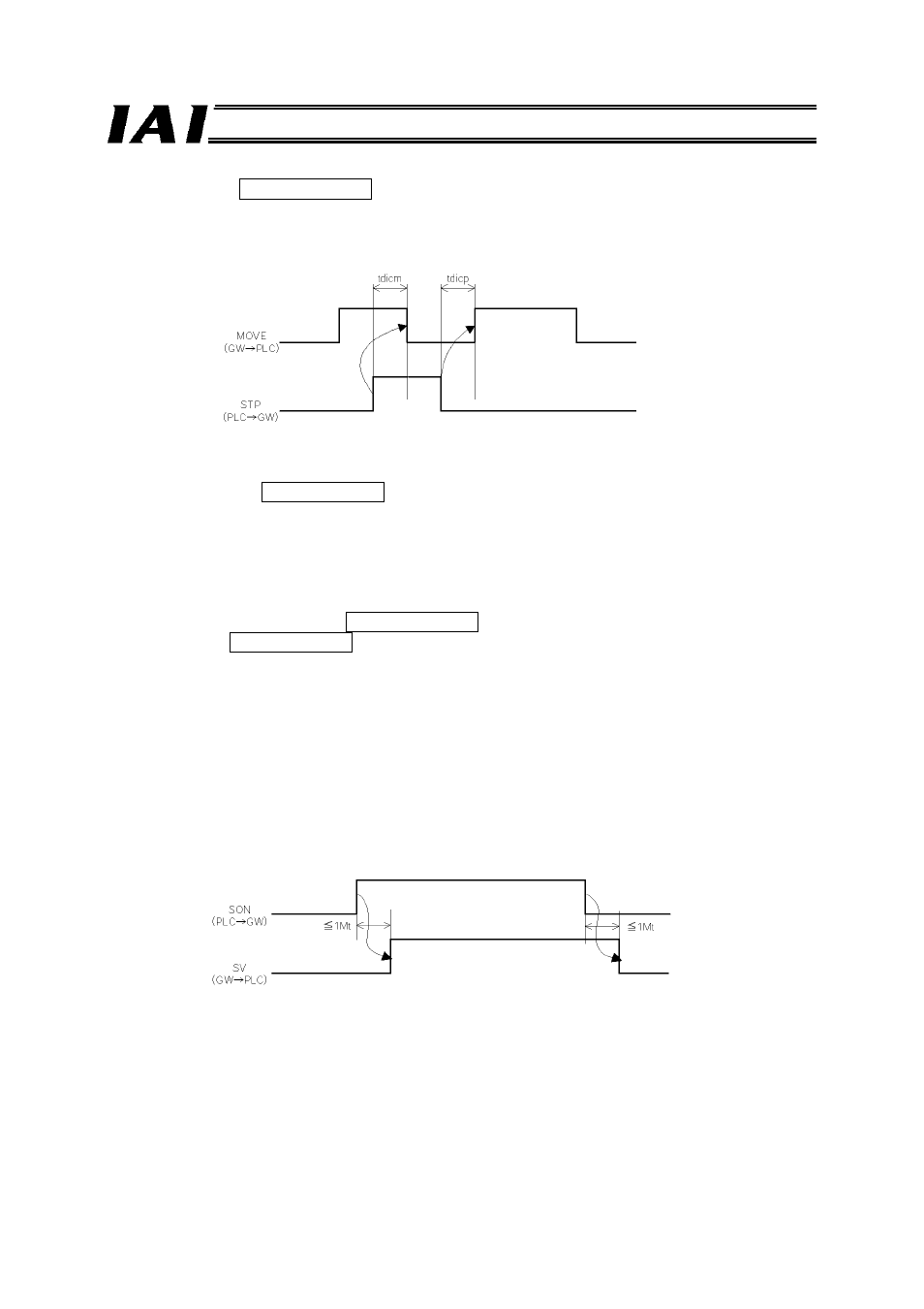
(5) Pause (STP) PLC output signal
Turning this signal “1” (ON) causes the axis to stop temporarily (decelerate to a stop). Turning it “0”
(OFF) resumes the axis movement.
The relationship of the STP signal and MOVE (moving) signal is shown below.
(6) Moving (MOVE) PLC input signal
This signal turns “1” (ON) while the actuator is moving with the servo turned on (and also during
home return, push-motion operation and jogging).
Use the MOVE signal along with PEND for status discrimination on the PLC side.
The MOVE signal turns “0” (OFF) upon completion of positioning, home return or push-motion
operation, and also while the actuator is paused.
(7) Servo ON command (SON) PLC output signal
Ready (SV) PLC input signal
Turning the SON signal “1” (ON) turns on the servo.
Once the servo turns on, the SV LED (green) on the front panel of the controller illuminates. With the
ERC2, the LED at the top of the motor unit illuminates in green.
The SV signal is synchronized with this LED indicator.
Function
The controller servo can be turned on/off using the SON (servo ON) signal.
While the SV signal is “1” (ON), the controller servo remains on and therefore the controller is
operational.
The relationship of the SON signal and SV signal is shown below.
tdicm
≤ Acceleration/deceleration
tdicp
≤ Yt + 2Mt + Xt + 6 (msec)