IAI America RCM-GW-PR User Manual
Page 50
44
PfofiBus Gateway
5.2.1 Overall
Address Configuration
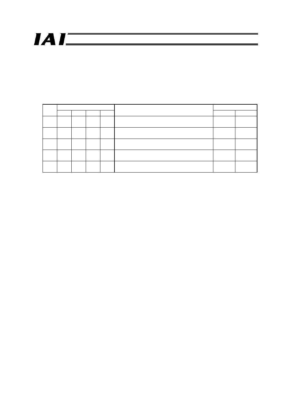
Four bytes are used by the gateway control signals, and also by the status signals, to be input/output.
In the direct numerical specification mode, the control signals of each axis consist of 12 bytes in the
PLC output area (gateway input area) and six bytes in the PLC input area (gateway output area).
The number of controlled axes is set by the mode setting switch (SW1), and the applicable data
areas vary depending on the setting of this switch. The switch settings and corresponding data areas
are shown below.
No.
SW1
I/O
bytes
4 3 2 1
Description
Output Input
1 X X X X
Direct numerical specification mode/Up to 4
axes can be connected
52 28
2 X {
X X
Direct numerical specification mode/Up to 6
axes can be connected
76 40
3
{
X X X
Direct numerical specification mode/Up to 8
axes can be connected
100 52
4
{
{
X
{
Direct numerical specification mode/Up to 10
axes can be connected
124 64
5
{
{
X X
Direct numerical specification mode/Up to 16
axes can be connected
196 100
{: ON X: OFF