IAI America RCM-GW-PR User Manual
Page 68
62
PfofiBus Gateway
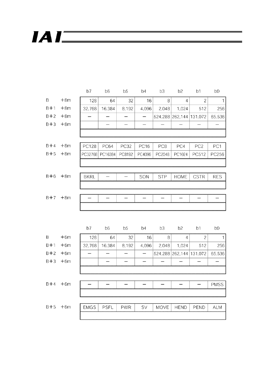
(2) Control/status signals for simple direct operation axis
Each axis consists of eight PLC output (control signal) bytes and six PLC input (status signal) bytes,
as shown below.
The position data specification and current position data signals use singed 32-bit hexadecimals
based on integers that are multiples of 0.01 mm.
* Byte address
B: Initial address of simple direct operation axis
m: Axis number assigned only to a simple direct operation axis (0 or greater), indicating each axis as the
nth axis from the first simple direct operation axis.
PLC output = Control signal
Byte address*
(Sign)
Position data specification (signed 32-bit integer)
Movement data position number
Control signal
(Cannot be used)
PLC input = Status signal
Byte address
(Sign)
Current position data (signed 32-bit integer)
Status signal
Status signal
- ERC2 (138 pages)
- ERC2 (188 pages)
- ERC3 (438 pages)
- ERC (153 pages)
- RCA-E (53 pages)
- RCA-P (42 pages)
- RCB-101-MW (38 pages)
- RCP2-C (178 pages)
- RCS-E (102 pages)
- RCA-A4R (72 pages)
- RCA-RA3C (114 pages)
- RCA-SRA4R (56 pages)
- RCA2-RA2AC (100 pages)
- RCA2-SA2AC (92 pages)
- RCA2-TA4C (134 pages)
- RCD-RA1D (40 pages)
- RCP2-BA6 (72 pages)
- RCP2-GRSS (130 pages)
- RCP2-HS8C (126 pages)
- RCP2-RA2C (120 pages)
- RCP2-RTBS (80 pages)
- RCP2W-SA16C (46 pages)
- RCP3-RA2AC (60 pages)
- RCP4-RA5C (82 pages)
- RCP4-SA5C (94 pages)
- RCP4W (96 pages)
- RCS2-F5D (142 pages)
- RCS2-GR8 (46 pages)
- RCS2-RN5N (80 pages)
- RCS2-RT6 (60 pages)
- RCS2-SA4C (258 pages)
- RCS2-TCA5N (62 pages)
- RCL-SA1L (66 pages)
- RCL-RA1L (56 pages)
- RCLE-GR5L (46 pages)
- IK Series (16 pages)
- FS (84 pages)
- IF (76 pages)
- ISB (114 pages)
- ISDA (126 pages)
- ISDB (116 pages)
- ISPWA (90 pages)
- ICS(P)A (16 pages)
- NS (78 pages)
- RS (46 pages)