IAI America RCM-GW-PR User Manual
Page 30
PRO
F
IBUS Ga
te
way
24
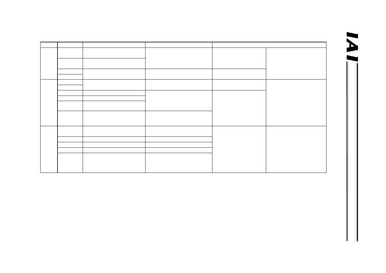
Symbol
Description
Specification
Connector and applicable wire
Pow
e
r-
s
u
p
p
ly
inp
ut conn
ector
24 V
Positive side of the 24-VDC
Gateway power supply
24 VDC
±10%
0.8 to 1.3 mm
2
The connection plug is a
standard accessory.
MC1.5/4-ST-3
y 5 (Phoenix
Contact)
N
Negative side of the 24-VDC
Gateway power supply
Power consumption: 300 mA
max.
AWG 18 to 16
S1
Teaching-pendant
emergency stop signal output
Allowable load voltage: 30 VDC 0.08 to 1.5 mm
2
S2
Allowable load current: 1 A
AWG 28 to 16
SIO
com
m
un
ic
a
tion
c
o
nn
ecto
r
PORT IN
External port switching input
No-voltage (dry) contact input
Load: 24 VDC, 7 mA
0.08 to 1.5 mm
2
AWG 28 to 16
The connection plug is a
standard accessory.
MC1.5/6-ST-3
y 81 (Phoenix
Contact)
The Gateway Unit has a
built-in terminal resistor, so
connect the terminal resistor
at the end of the SIO
communication line.
PORT N
SDA
SIO communication line A
Align the potential level of the
connected controller or ERC
actuator with the potential level
of the GND (ground).
Double shielded twisted-
pair cable (AWG22)
Recommended cable:
HK-SB/20276 X L
2P X AWG22 by Taiyo
Electric Wire & Cable
SDB
SIO communication line B
GND Ground
FG Frame
ground
Internally connected to the
frame.
Pro
fiBus
c
o
mmu
nicatio
n
co
nne
cto
r
B-Line
Communication line B
(RS485)
ProfiBus-DP type A cable
(2-core twisted pair cable
with shield)
The connection plug should
be a D-sub, 9-pin connector,
but this plug is not supplied.
With ProfiBus, a terminal
resistor*1 must be
connected to both ends of
the trunk line. For details,
check the operation manual
for the master (PLC).
RTS Request
to
send
GND
Signal ground (insulated)
+5V
+5-V output (insulated)
A-Line
Communication line A
(RS485)
*1 The gateway unit has a built-in terminal resistor. Set the terminal switch ON/OFF to enable/disable this built-in terminal resistor.
(3)
I/O
s
ignal sp
e
cific
ations
and
w
ires