IAI America RCP2W-GRLS User Manual
Page 121
111
1
1. Appendix
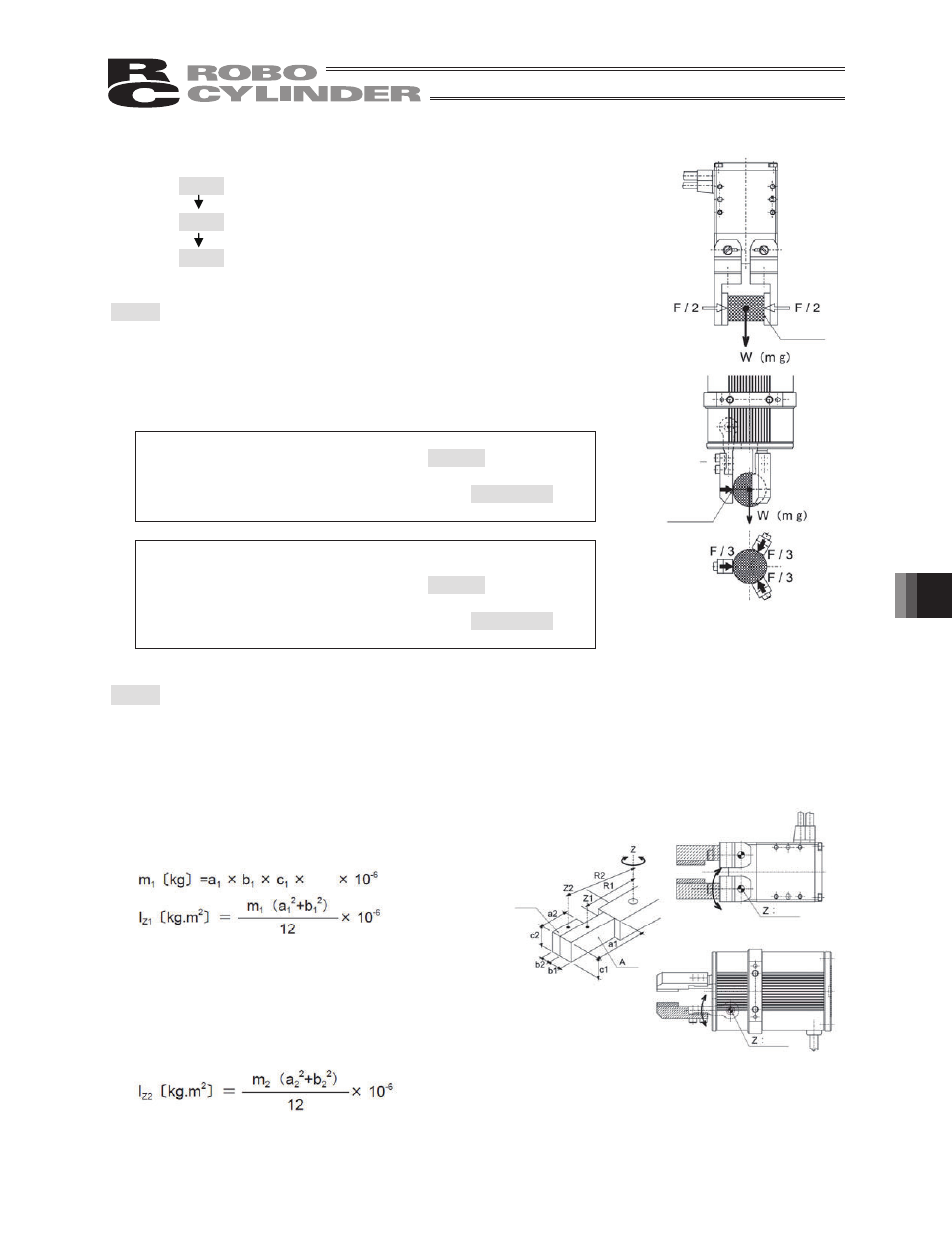
11.1.2 Lever
Type
Step 1: Check the required gripping force and work part mass that
can be transferred
Step 2: Check the inertial moments applied to the finger attachment
(finger)
Step 3: Check the external forces applied to the finger
Step 1: Check the required gripping force and work part mass that can be
transferred
Calculate the required gripping force by following the same
operation in step 1 explained for the slide type, to confirm that the
required condition is met. Calculate the effective gripping force at
the gripping point by referencing 5.3, “Adjusting the Gripping Force.”
Normal transfer of work part
Required gripping force
At least 10 to 20 times the
mass of the work part.
Work part mass that can
be transferred
No more than 1/10 to 1/20 of
the gripping force
When a high acceleration/deceleration or large impact
force is applied
Required gripping force
At least 30 to 50 times the
mass of the work part
Work part mass that can
be transferred
No more than 1/30 to 1/50 of
the gripping force
Step 2: Check the inertial moments applied to the finger attachment (finger)
The finger shall be designed in such a way that the total inertial moment that generates around the Z-
axis (fulcrum) of the finger attachment (finger) will remain within the allowable range. Calculate the
total moment by dividing it into multiple component moments according to the finger configuration
and shape. For your reference, a calculation example is given below where two component moments
are calculated.
(1) Inertial moment around the Z1-axis (center of gravity of A) (A)
m
1
:
Mass A [kg]
a,b,c: Dimensions of A [mm]
(2) Inertial moment around the Z2-axis (center of gravity of B) (B)
Friction
coefficient
P
Fulcrum
Specific
gravity
Fulcrum
Fulcrum
B
Friction
coefficient
P