Boom / head installation – Alamo TS-100A User Manual
Page 89
© 2005 Alamo Group Inc.
Section 9 - 7
Maverick (NH TS-100A,115A, 125A, 135A Asy. Man) 01/05
Boom / Head Installation
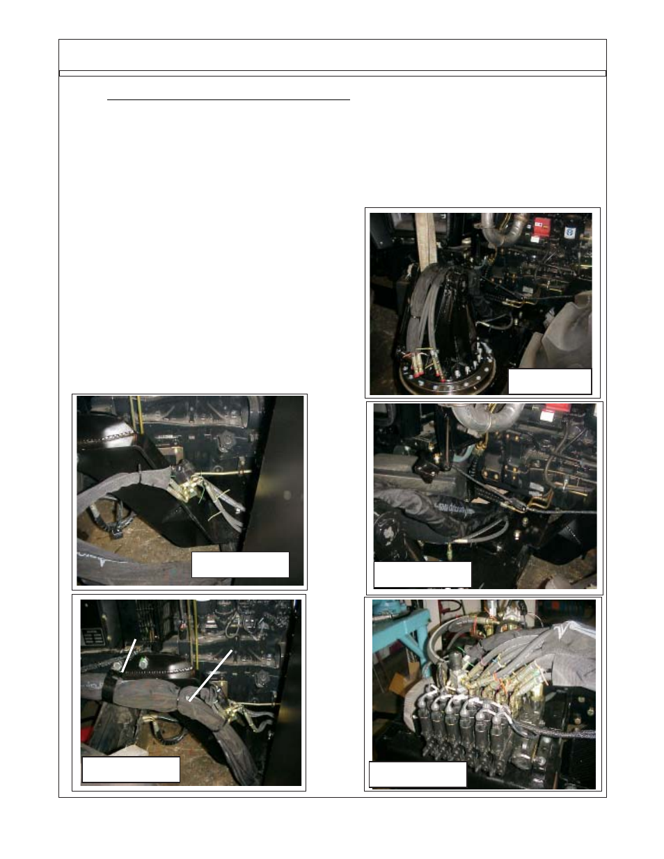
The other cylinder hoses from the boom will
be inserted into sleeving material and also be routed
under the tractor to the LH side (See Figure 14). They
will continue up the LH side to the front of the tractor
where they will connect to the valves ports. The
hoses will be held to the frame with metal hose hold-
ers bolted to the tractor frame (See Figure 15).
NOTE: the hoses must be run through the
sleeving material. On the LH side there is a hole in the
center frame weldment the hoses can be run through
it if wanted. Connect the hoses to the valve as shown
(See Figure 11 & 17)
Figure 12
Figure 13
Figure 14
Figure 15
11.
Routing Cylinder Hoses from Boom to Valve The Hose from the boom to the valve will be
split, the four hoses to the door cylinder and swivel cylinder will run together through a section of
sleeving material to the RH side of the tractor (See Figure 12). On the Right hand side of the
tractor the four hoses will connect to the diverter valve in the coded locations (See Figure 11). Tie
the hoses to the frame under the tractor (See Figure 13). The two hoses from the diverter valve will
continue along the LH side of tractor with sleeving material over them (See Figure 13) to the front
of the tractor. They will have hose support brackets on them that bolt to the side of the tractor (See
Figure 13) where they will be connected to the valve at the Door / Swivel Ports in the correct order
(See Figure 16 & 17).
Figure 16
Sleeving Material
for Hoses
Hose Support
Bracket