Figure 25, Figure 26 – Alamo TS-100A User Manual
Page 75
© 2005 Alamo Group Inc.
Section 8 - 11
Maverick (NH TS-100A,115A, 125A, 135A Asy. Man) 01/05
Exterior Wire Harness Schematic P/N 02981375A
Plug
Valve
Valve
Label Function
Label
AA1
Swivel
B
AA2
Swivel
A
AA3
Tilt
A
AA4
Tilt
B
AA5
Telescope
A
AA6
Telescope
B
AA7
Dipper
A
AA8
Dipper
B
AA9
Lift
A
AA10
Lift
B
AA11
Swing / Door
A
AA12
Swing / Door
B
X1 & X2
(Return Filter)
E (XT2 Module)
S1 (Temp Sensor)
R1 (Cooler Fan)
G2 (Plug to Interior
Wire Harness)
Y1 Connect to White Wire & Y2 Connect
to Black Wire ( Valve Filter)
W1 (Charge Filter)
F (XP2 Module)
H1 & H2 ( Lock Valve Connection)
AA (See
Below)
BB (Diverter Valve)
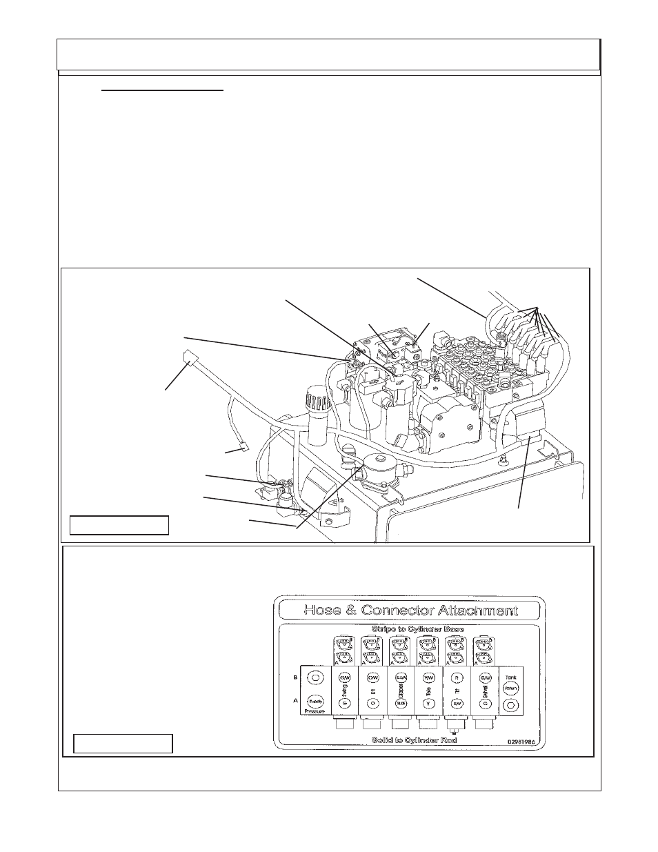
FIGURE 25
13.
Exterior Wire Harness. The exterior wire harness will run from the cab of the tractor to the front.
It will include the wiring for the sensors at the pump. The connections for the valve actuator assemblies.
The electronic modules that are mounted to the right side of the tank and the module on the front of the
valve. The plugs have codes labeled on them, there is a matching code on them where the plugs are
connected. Some plugs have instructions and/or color codes. Read the next pages of this manual to
become familiar with the wire harness connections. There are two electronic modules bolt on the tank
assembly in the front of the tractor. The XT2 module bolted on the right hand side of the tank and the XP2
bolt on the LH side in front of the 6 spool valve. (See Figure 25, 27 & 28). The exterior wiring harness should
be laid out and connections need to be start at the first connection coming from the tractor cab connection,
this allows the harness to be moved around and under components as needed.
NOTE; V1 Pump Solenoid 2 is only used when the Timbercat Head is installed and will be installed into
plug next to Pump solenoid 1 which is used with all heads. Note: Unless the timbercat head is used only
Solenid 1 will be installed which is Plug V1, leave plug T1 tie to othrer plug out of the way.
NOTE; Decal, Stripes to Base and Solid to Rod end refers to the plastic ties on hoses only &
not electricl connections
Decal Below shows the Hose location and Plastic tie color on hose.
Also the markings for the wire harness plugs on valve ("A" or "B")
See Figure 18 & 18A)
FIGURE 26
Pump Solenoid
T1 (Sol 2) & V1(Sol1)