Six spool control valve, Figure 28, Figure 30 – Alamo TS-100A User Manual
Page 77: Figure 29
© 2005 Alamo Group Inc.
Section 8 - 13
Maverick (NH TS-100A,115A, 125A, 135A Asy. Man) 01/05
14.
Diverter Valve Wiring Connection: The plug for the diverter valve is at the end of the exterior
wiring harness and will be marked with code BB. The plug and wire will run down the LH side of tractor
from the front mounted hydraulic pump / Tank. The diverter valve is bolted the the LH front Frame
Mount bracket. The holes are already in the bracket and the diverter valve should have already been
mounted. If valve has not been mounted it can be mounted now (See Figure 27, 28 , 31 & 38).
Exterior Wire Harness Schematic P/N 02981375A
Pressure
Supply
Port "P"
Return
To Tank
"T"
"B"
"A"
"A"
"A"
"A"
"A"
"A"
"B"
"B"
"B"
"B"
"B"
Swing
Lift
T
e
lescope
Head T
ilt
Head Swivel / Door
(T
o Diverter V
alve)
Dipper
G
G/W
OR
R/W
Y/W
B/W
OR/
W
Y
R
B
G/W
G
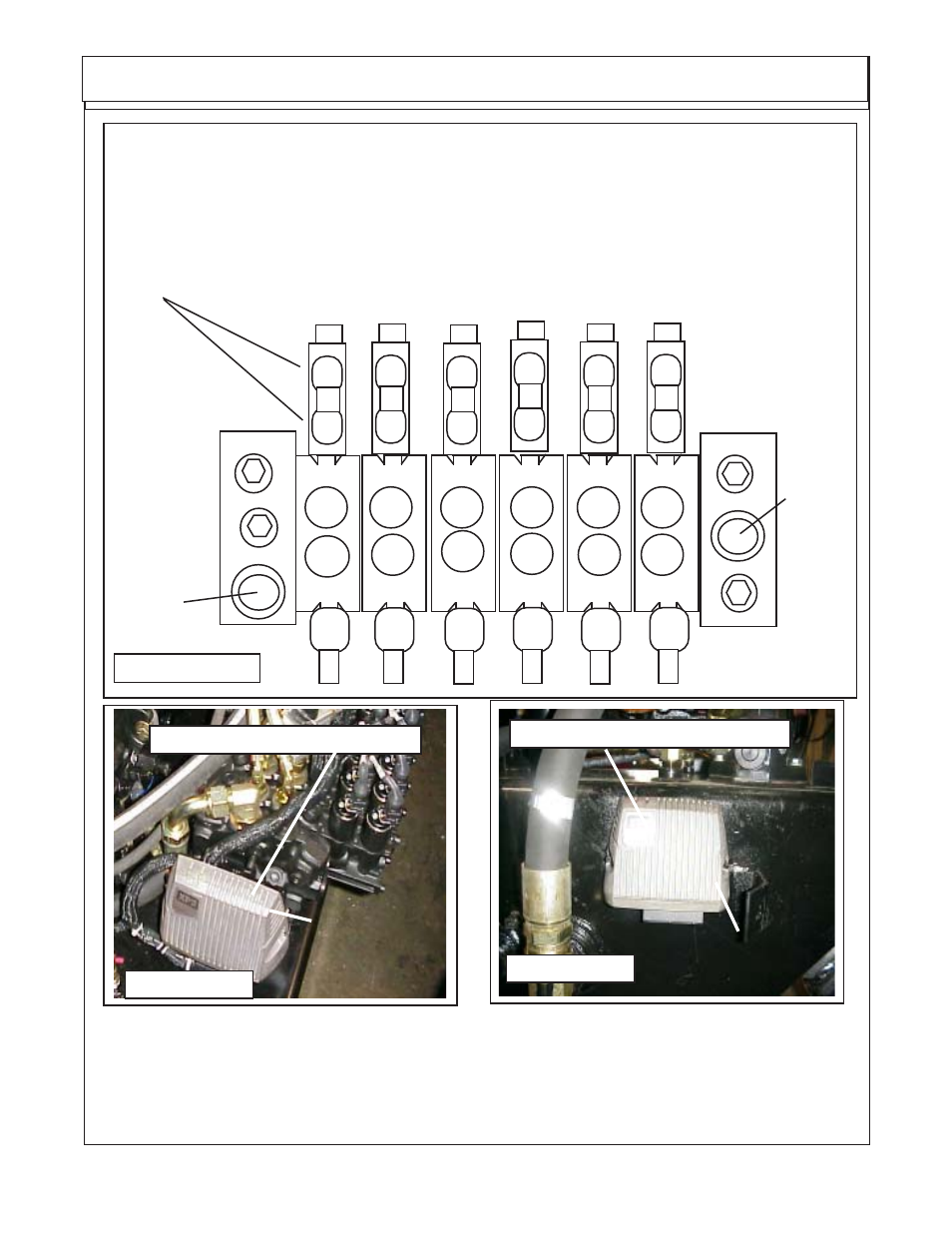
Six Spool Control Valve
FIGURE 28
External Wire Connec-
tions for valve are marked
"A" and "B" on Valve &
AA1 thru AA12 on wire
harness connections
A A
11
A A
12
B
A
A A
9
A A
10
B
A
A A
7
A A
8
B
A
A A
5
A A
6
B
A
A A
3
A A
4
B
A
A A
2
A A
1
B
A
XT2 (Expansion, Transmission)
FIGURE 30
Bolts on RH side
on side of Tank
XP2 (Expansion, Power)
Bolts on LH side
in front of Valve
FIGURE 29