Interior xs module & display control box, K3 x1 – Alamo TS-100A User Manual
Page 74
© 2005 Alamo Group Inc.
Section 8 - 10
Maverick (NH TS-100A,115A , 125A, 135A Asy. Man) 01/05
Interior XS Module & Display Control Box
10.
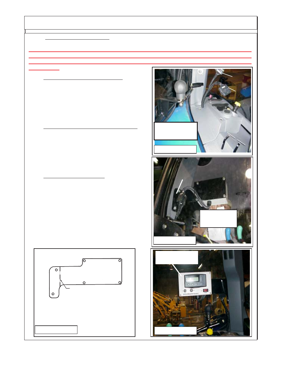
Tractor RH Side Panel reinstalled. When the
tractor side panel is reinstalled the plugs (2 Plugs K3 &
X1) for the Display control box will be sticking up out from
be hind the panel (See Figure 21), Run the wiring harness
in from behind panel, use caution to not let wire harness
interfere with or be in a position to damage or be damaged
by other tractor components behind panel.
11.
Install Display Control Box Mount Bracket. The
display mount control box mount to the Rh rear cab post
(See Figure 22 & 23) . There are two plastic plugs in the
plastic cover over cab post. Remove these two plug to
expose two 10 mm bolt holes in cab post. Position the
mounting bracket with the bent end at the post and using
the 10 mm bolts furnished bolt the bracket to the post.
12.
Install Display Control Box. The display control
box will bolt to the mount plate P/N 02982324 that is
mounted to the RH Rear Cab corner post (See Figure 22,
23 & 24). There is a wire setion on disply control box that
will pug into the two plugs on the interior harness plug KS
& X1 (See Figure 21 & 22)
The display control box cannot be tested until the interior
and exterior wiring harness installation has been com-
pleted and all the other installations of unit have been
done. DO NOT reconnect battery cables at this time, the
electrical wiring is NOT done.
Bend Upward 60° Here
P/N 02982324 Mount
Plate - (Iqan) Display
Control Box Mount
FIGURE 23
9.
Connect Wires to Key Switch. There are two wires on the interior Harness that connects to the
key switch (Wires CC1 and CC2) these need to be routed under floor mat and in behind dash panels.
CAUTION:The positeve wire (CCI) MUST be connected to the wire from the key ignition switch
of tractor for an electrical power supply. DO NOT connect the power supply wire (CC1) to any
other power supply as it could cause interference with the electronic components due to a
power surge
FIGURE 24
Display
Control Box
Cab RH Rear
Corner Post
FIGURE 22
P/N 02982324 Mount
Plate - (Iqan) Display
Control Box Mount
FIGURE 21
Display Control
Box Connections
K3
X1