Figure 14 – Alamo TS-100A User Manual
Page 71
© 2005 Alamo Group Inc.
Section 8 - 7
Maverick (NH TS-100A,115A, 125A, 135A Asy. Man) 01/05
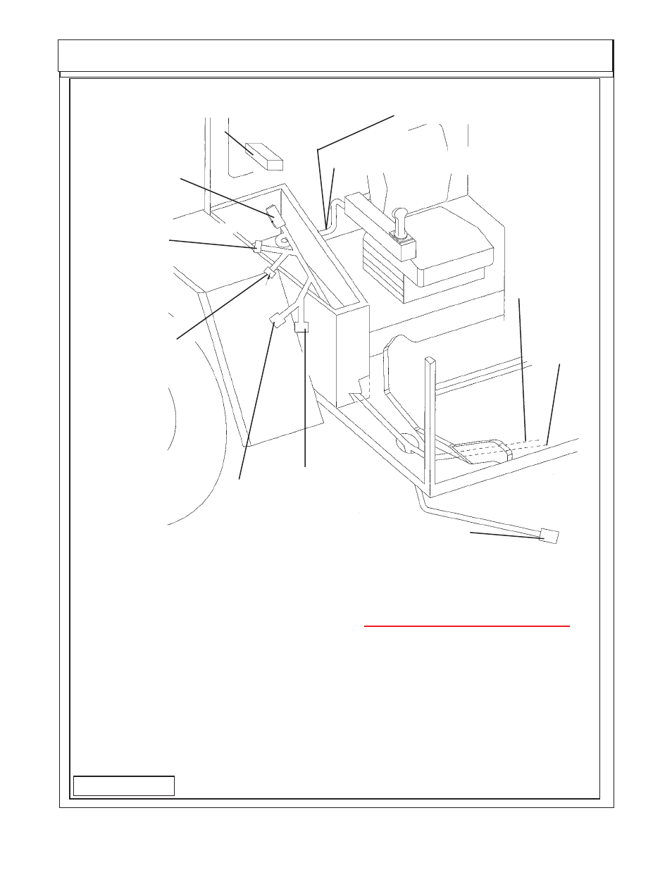
Interior Wire Harness Schematic P/N 02981375B
G1 (Connects to G2 Plug
of Exterior Wire Harness)
CC1
+Pos.
Key Switch
Connection
CC2 - Neg.
Chasis
Ground
X1 ( Control
Box Display
Connection
K3 ( Control
Box Display
Connection
D ( XS Module
Connector)
Can 1 ( XS
Module
Connector)
Can 2 ( XS
Module
Connector)
J1 Joystick Connection (9 Pin)
P1 Joystick Connection (6 Pin)
Remove console cover, tie strap
XS Module P/N 02981533 inside
console
Code
Connection
Can 1
XS Module Can1 Connection (2 of 3 Connections)
Can 2
XS Module Can 2 Connection (3 of 3 Connections)
CC1
+ Positive Key Switch Connection
(MUST Connect to key switch wire)
CC2
- Negative Chasis Ground
D
XS Moudule C1 Connection (1 of 3 Connections)
G1
Exterior Harness G2 Plug (coonnects Interior & exterior Harness)
J1
Joystick Resister Harness (9 Pin Plug)
K3
Control Box Display Connection (1 of 2 Connections)
M1
E-Stop Switch (use A or B of Switch)
M2
E-Stop Switch (use A or B of Switch)
X1
Control Box Display Connection (2 of 2 Connections
FIGURE 14