Boom / head installation – Alamo TS-100A User Manual
Page 84
© 2005 Alamo Group Inc.
Section 9 - 2
Maverick (NH TS-100A,115A, 125A, 135A Asy. Man) 01/05
Boom / Head Installation
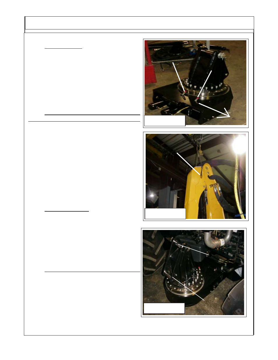
Figure 1
Swing Cyl. Hose
with Green /
White Tie
Swing Cyl. Hose
with Green Tie
Rear of Tractor
Boom Installation / Boom Hoses:
1.
Turret Assembly, The turret assembly has
the cylinders connected and the hoses are con-
nected to the cylinders. The end of the hoses will
be sticking up through the turret mount weldment
between turret and tractor. The hoses will need
to be connected there and routed to the hydraulic
control valve. One hose will have a Green Tie
and one a green and white tie where the come up
throught the turret mount weldment. (See Figure
3).
2.
Booms Are recieved from the factory with
the Sections of Boom Assmebled to together.
The Boom Sections are assembled with the hy-
draulic lines and cylinder connected. The hose
will be connected to the boom that are routed to
the control valve and diverter valve and bundled
together.
(See Figure 4). The Boom Hoses are
protruding out the turret mount end of the boom.
The Hose connections on the head end will be
shipped with metal caps on them, these are to
protect the lines from contamination and should
not be removed until the hoses are being in-
stalled (See Figure 5). The hose that attaches to
the boom are sent installed on the head assem-
bly and the hose will also have plugs in them.
3.
Boom Lift Cylinder. The boom lift cylinder
will be connected to the boom at the rod end of
the cylinder (See Figure 2 & 4) when it is shipped
from factory. The hoses will also be connected to
the cylinder. The retaining pin for the lift cylinder
will be located in the turret assembly. The Lift
Cylinder will be fastened to boom with tie wire. It
will not be required to remove this tie wire before
mounting boom on turret assembly.
-
4.
Booms & Lift Cylinder Mounting Pins.
The Boom and lift cylinder mounting pins are
shipped installed in the turrert assembly. Re-
move both pins in preparation to mounting the
boom. (See Figure 3)
Figure 3
Main Boom
Mount Pin
Lift Cyl. Base
End Mount Pin
Figure 2
Lifting
Point