Joystick / electrical mounting – Alamo TS-100A User Manual
Page 69
© 2005 Alamo Group Inc.
Section 8 - 5
Maverick (NH TS-100A,115A, 125A, 135A Asy. Man) 01/05
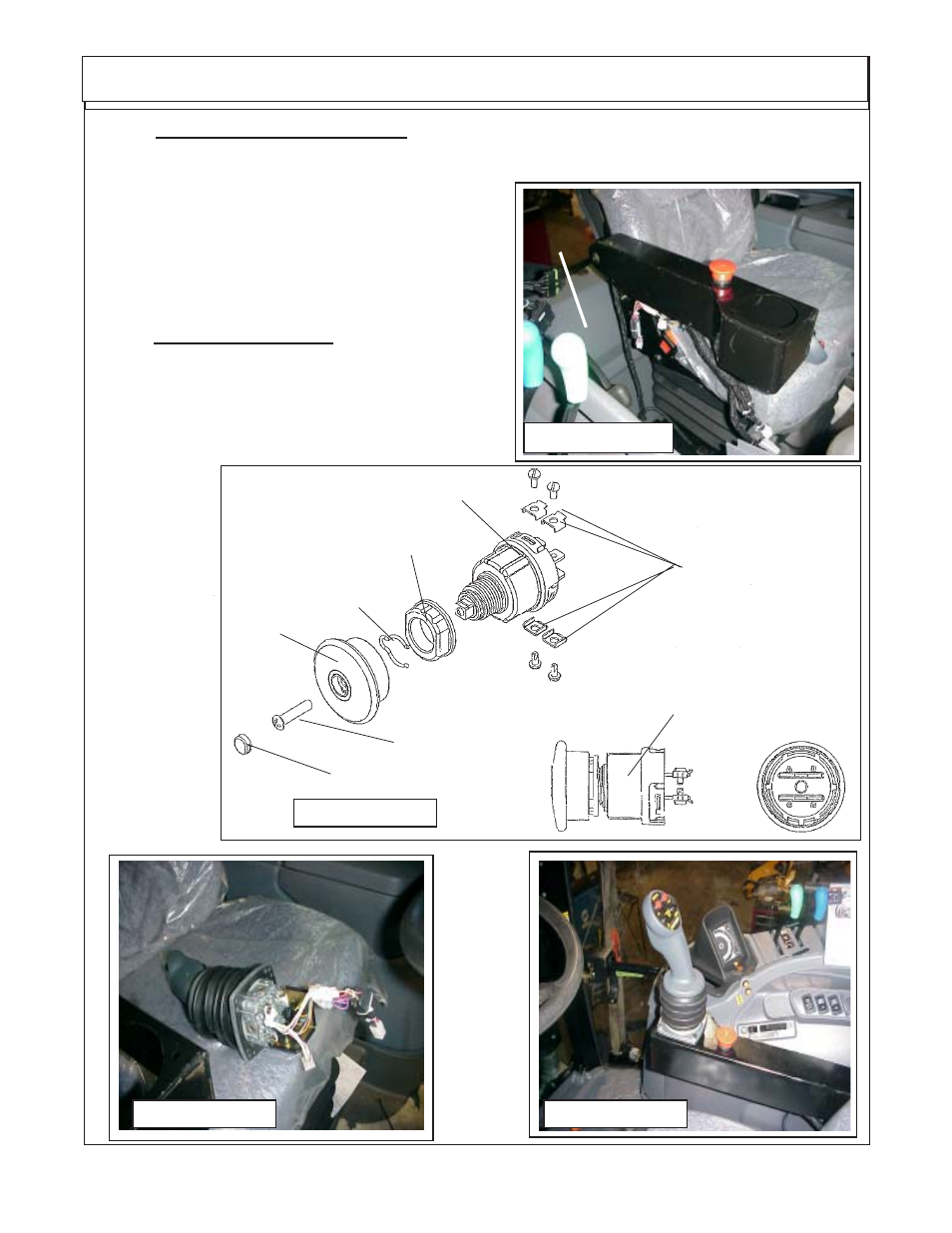
FIGURE 9
when the interior harness is installed. (See Figure 7 &
8). The Interior harness is run under the RH side Panel
and along the rear panel. You will need to cut a notch in
the rear panel to allow the harness to pass between the
two panels where they meet near the bottom.
5.
Interior Wire Harness. The interior wire har-
ness has all the connections needed to connect interior
components. The RH side interior panel of cab will need
to be loosened and/ or removed, this allows mounting of
the XS module (See Figure 6 & Next pages for wiring
schematics) continued in step 6
FIGURE 7A
Joystick / Electrical Mounting
Knob Plug
Knob Retaining
Screw
Knob
Depth Control Clip
Switch Mounting Nut
Switch
Wire Fasteners (4)
Switch Asy Complete
FIGURE 8
4.
Resister Harness to Joystick. The Joystick will be shipped with the resister Harness
connected to it as an assembly. (See Figure 7 & 8) The Interior wire harness plug has 2 connectors
on it A 9 Pin Connector (labeled J1) and a 6 Pin Connector (labeled P1) . These two connections will
plug into the interior wire harness with the same code
Rear
Panel
FIGURE 10