Control valve - joystick, Joystick functions, Figure 18 – Alamo TS-100A User Manual
Page 106
© 2005 Alamo Group Inc.
Section 10 - 12
New Holland (NH TS-100A, 115A, 125A, 135A Asy. Man) 01/05
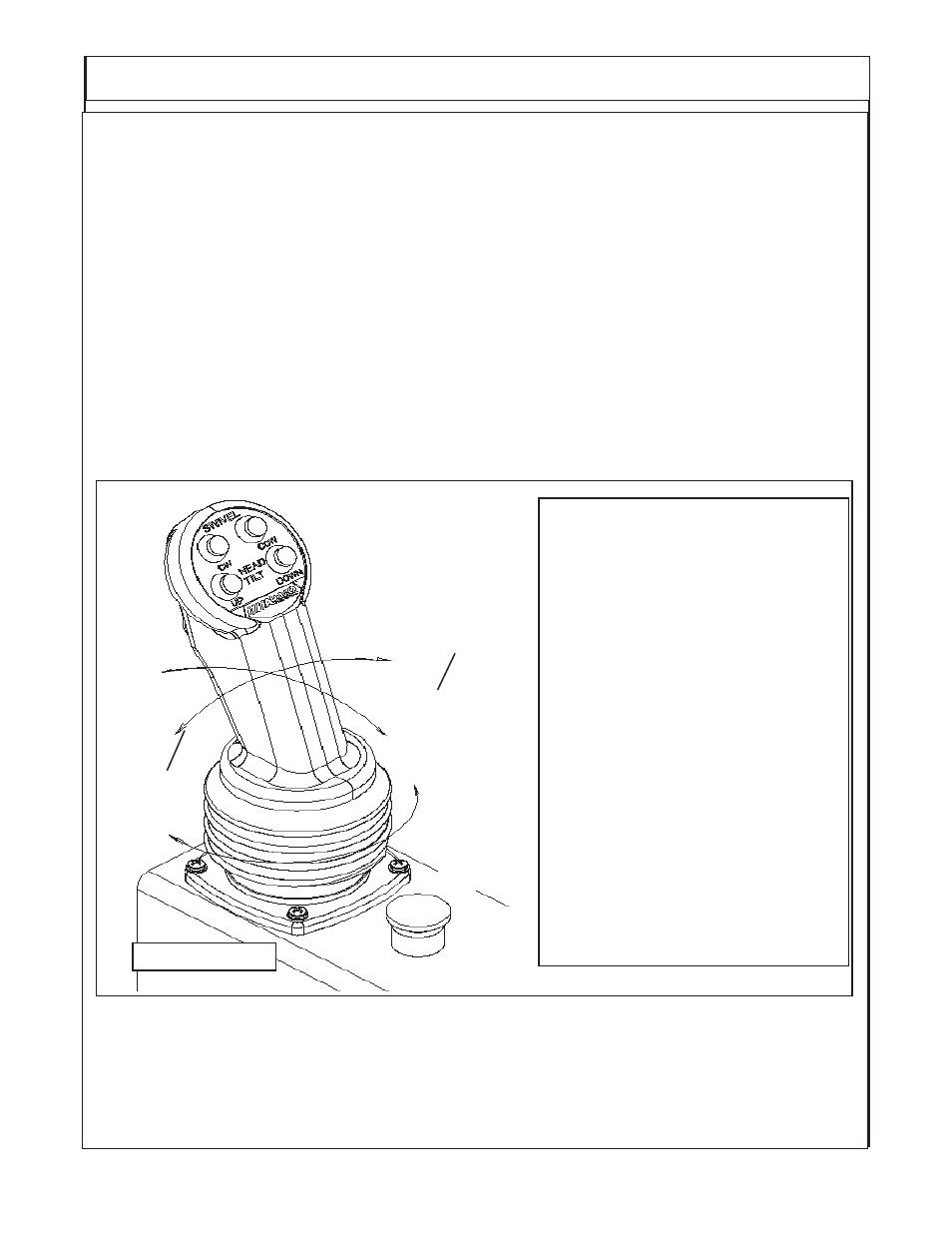
JOYSTICK FUNCTIONS
: (Figure 18)
To operate a function the following series of events must work.
1. The Joystick Controller is moved in the correct direction the required distance, During its movement
an electrical signal is sent to the electric Controller in the proper Valve Section of the Control Valve.
2. The Electric Controller sends an electrical signal, which causes the Proportional Control Valves to
actuate the proper amount based on the signal from the Controller. EXAMPLE: Valves 1 & 3 allow
Pilot Pressure Oil to flow to the corresponding end of the Spool, Thus causing it to move. Valves 2
& 4 allow the Oil from the opposite end of the Spool to return to the Tank. (NOTE: Lift, Swing and
Dipper functions are Proportional, Door and Tilt functions are “ON” or “Off” Only, See later section
for explanation of Proportional).
3. The Spool position Transducer sends an electrical signal to the Electronic Controller which indicates
the position of the Spool.
4. The Electronic Controller will continue to adjust the Valves (1 - 4) in order to maintain an equilibrium
between the Joystick signal and the feedback signal.
5. Reaction time from the time the Joystick is moved until the Spool moves is approximately 300
milliseconds.
Joystick Functions
Push Buttons Only
Top Left
=
Swivel CW
Top Right
=
Swivel CCW
Bottom Left
=
Tilt Up
Botom Right
=
Tilt Down
Push Button & Trigger Switch
Top Left
=
Door Open
Top Right
=
Door Close
Handle Movement
Push Front
=
Lift Down
Pull Back
=
Lift Up
Push Right
=
Dipper Up
Push Left
=
Dipper Down
Rotate Right
=
Swing Back
Rotate Left
=
Swing Forward
Trigger & Handle Movement
Push Right
=
Telescope Out
Push Left
=
Telescope In
Trigger + Dipper = Telescope
Trigger + Swivel = Door
Trigger
Lift
Down
Dipper
Down
Tele
In
Lift
Up
Swing
In
Dipper
Up
Tele
Out
Swing
Out
Run
E-Stop
Stop
FIGURE 18
The Joystick is P/N 02981374. The Plug in connections are marked with numbers on the plastic plug.
The wires are solid color or a color with a stripe. The Plugs should not fit but one way and that is by
matching the codes on the plugs.
CONTROL VALVE - JOYSTICK