Frame installation – Alamo TS-100A User Manual
Page 53
© 2005 Alamo Group Inc.
Section 5 - 13
Maverick (NH TS-100A,115A ,125A/,35A Asy. Man) 01/05
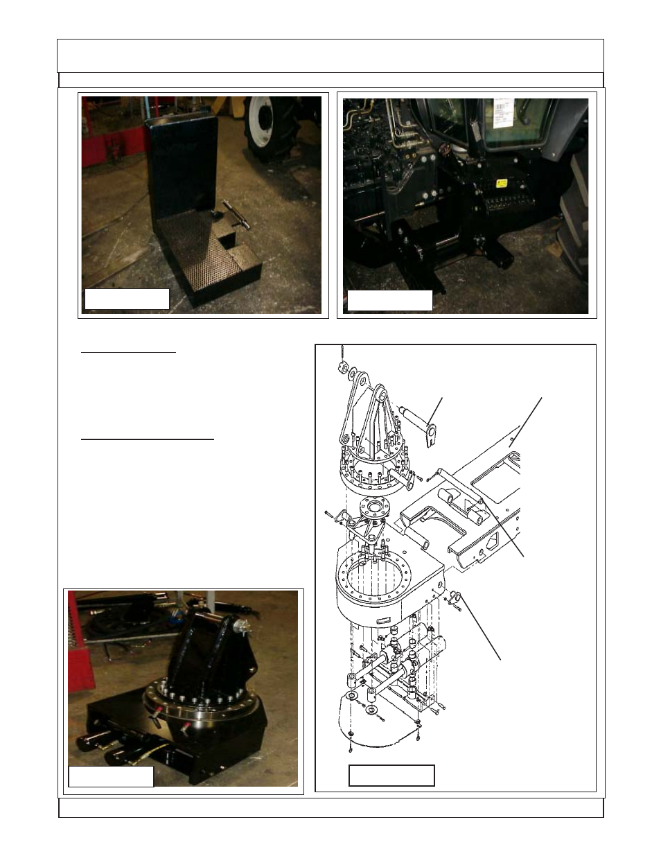
Figure 34
Figure 33
Frame Installation
Turret Assembly Installation 24 & 30 Foot Boom:
1.
Turret Assembly. Theturret assembly is
shipped assembled with the hydraulic swing cyl-
inders, hoses, pivot bearing assembly, boom
mount weldment and mounting pins installed
(See Figure 35 & 36).
2.
Under Frame Weldment. The Under frame
weldment center section is designed for the turret
assembly to mount on the RH side. Remove the
one long mounting pin and the front and back
short mounting pins (See Figure 36 & 37). Check
to make certain the mounting bolts mounting the
center ubder frame weldment are installed with
the bolt heads unter frame weldment and nuts are
on top visible looking down, if they are in wrong the
swing cylinders will hit the bolts causing damge to
cylinders and bolts. (See Figure 37)
Figure 36
Figure 35
Turret Attach-
ing Pin, Short
Pin, one Front
side and one
rear side.
Center Section
Under Frame
Weldment
Turret Mount
Attaching Pin,
Long Pin
Turret Mount
Attaching Pin,
Long Pin