Connection of the positioner type 8694 – Burkert Type 8694 User Manual
Page 45
45
Electricalinstallation24VDC
10.2.2. Connection of the positioner Type 8694
→
Connect the pins according to the model (options) of the positioner.
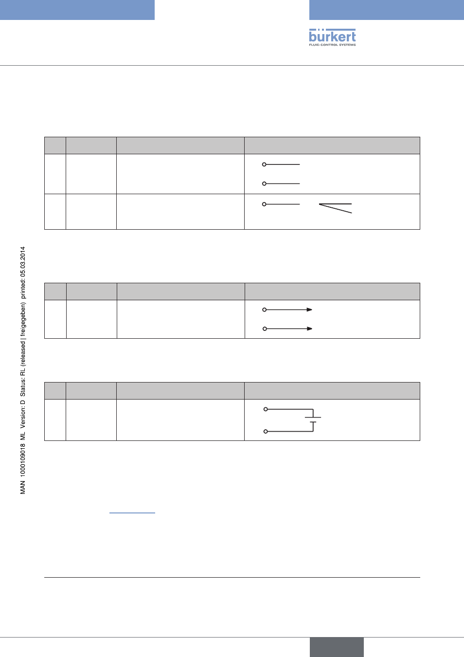
Input signals of the control center (e.g. PLC) - circular plug M12 x 1, 8-pole
Pin
Wire color
15)
Configuration
external circuit / signal level
1
2
white
brown
Set-point value + (0/4 – 20 mA)
Set-point value GND
1
2
GND
+ (0/4 ... 20 mA)
5
6
grey
pink
Binary input +
Binary input GND
5
+
0 ... 5 V (log. 0)
10 ... 30 V (log. 1)
identical to Pin 3 (GND)
Table 15:
Pin assignment - input signals of the control center - circular plug M12 x 1, 8-pole
Output signals to the control center (e.g. PLC) - circular plug M 12 x 1, 8-pole
(required for analogue output option only)
Pin
Wire color
15)
Configuration
external circuit / signal level
8
7
red
blue
Analogue position feedback +
Analogue position feedback GND
8
7
GND
+ (0/4 ... 20 mA)
Table 16:
Pin assignment - output signals of the control center - circular plug M12 x 1, 8-pole
Supply voltage (circular plug M12 x 1, 8-pole)
Pin
Wire color
15)
Configuration
External circuit
4
3
yellow
green
+ 24 V
GND
4
3
24 V DC ± 10 %
max. residual ripple 10 %
Table 17:
Pin assignment - supply voltage (circular plug M12 x 1, 8-pole)
When the supply voltage is applied, the positioner is operating.
→
Make the required basic settings and actuate the automatic adjustment of the positioner, as described in the
chapter entitled “12. Start-up”.
15)
The indicated colors refer to the connecting cable available as an accessory (919061)
English
Type 8694