Dual dim installation, Hardware configuration, Device address – Franklin Fueling Systems T5 Series Fuel Management System Programming Guide User Manual
Page 50: Communication settings
46
Dual DIM Installation
Some sites and dispenser configurations may require
the use of a second DIM module that would be installed
externally to perform reconciliation or VRM. This section
outlines the special installation steps required to install a
second TS-DIM on a T5 series console.
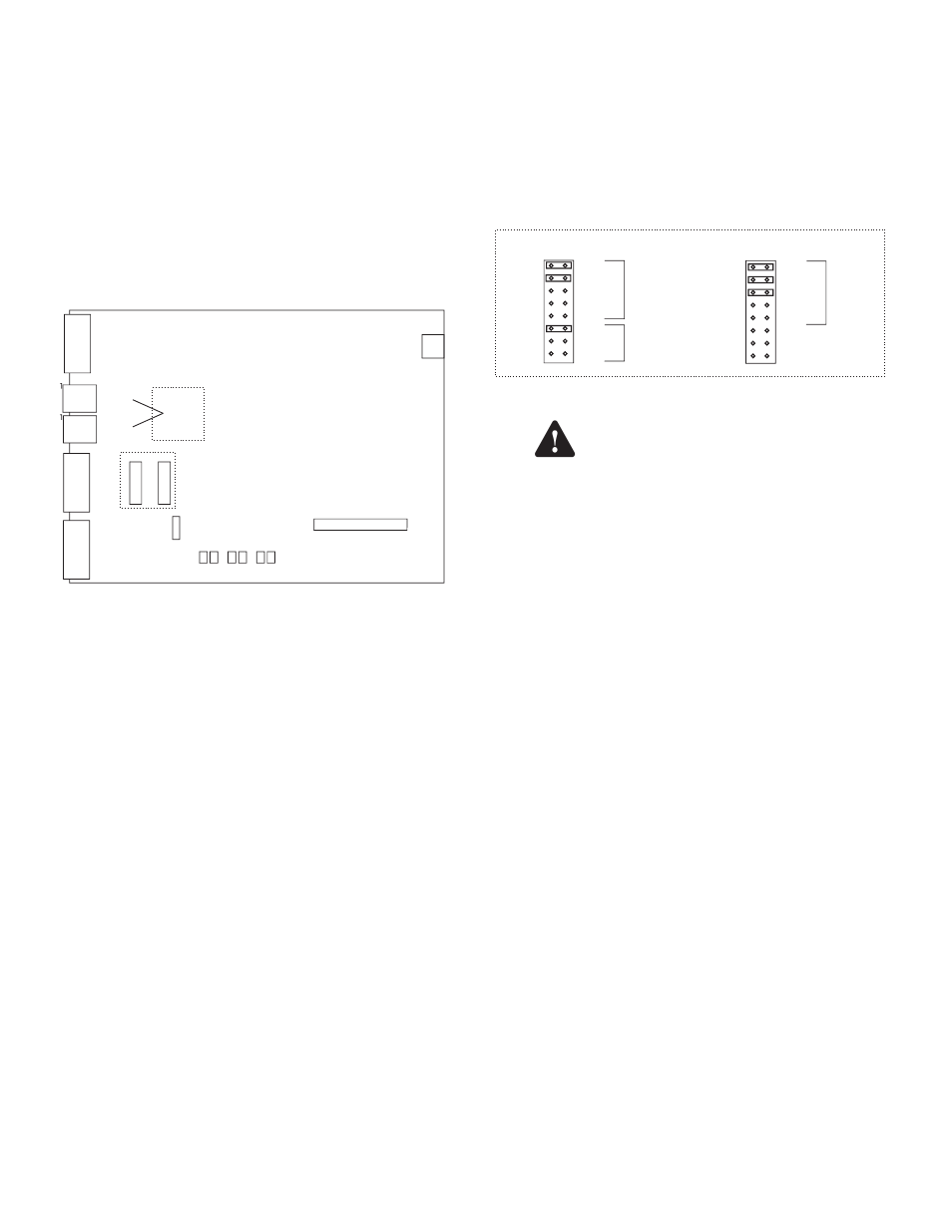
Hardware Configuration
In order for the external TS-DIM module to communicate
properly with the T5 series console a few jumpers will
need to be adjusted. To make these adjustments the cover
of the TS-DIM will need to be removed to access the
jumpers.
J8
AC pwr
J3
Diagnostic Port
J5 RS485 Link to next box
J4
Host1/ Rs485
Pinouts for
J4 & J5
A 1
B 3
GND 2
J2
Auxilliary/RS232
W2
1
2
3
4
5
6
7
8
W1
1
2
3
4
5
6
7
8
W3
+
-
RTS
J1
Host1/RS232
Tx Rx Tx Rx Tx Rx
Diag Host1 Aux
1 Adapter Connector
J6
Top View of TS-DIM Main Board
2 10
1 9
2 10
1 9
Device Address
The internal DIM module in the T5 series console will
always be addressed as zero. By default an external TS-
DIM will come shipped with an address of zero also. For
these two devices to exist on the same system the external
TS-DIM will need to have it’s address changed to one. Set
the external TS-DIM’s address to one by placing a jumper
on row 6 of W2.
Communication Settings
Once the external DIM has been addressed properly
the communications for the Host 1 port will need to
be changed to match the internal DIM communication
settings. The internal DIM’s communication settings
are: 9600 Baud Rate, 8 Data Bits, No Parity. To
properly configure the communication setting
on the external DIM you will need to place
jumpers on the following rows 1, 2, and 3 of W1.
W1
1
2
3
4
5
6
7
8
BR 1
BR 2
DB (7/8) Host 1
P 1
P 2
Reserved
Reserved
Reserved
Jumper Detail
W2
1
2
3
4
5
6
7
8
BR 1
BR 2
DB (7/8)
P 1
P 2
A1
A2
A3
Aux
Device
Address
Wiring the TS-DIM to a T5 Series Console
Turn off the main power source / all
power sources that terminate in the
console before working on or servicing
this equipment. Failure to do so will
create a lethal electrical shock hazard.
1. Make sure all power to the T5 Series console is
turned off at the power source.
2. Locate the Communication Ports on the T5 series
console.
3. Terminate the wires as follows:
a. Wire 485A to Terminal 485A
b. Wire 485B to Terminal 485B
c. Wire S.RTN to Terminal GND
Note: There may be RS-485 interface wires already
connected to the terminals. In this case, remove
the wire(s) and splice them with the appropriate TS-
DIM wire. Reinsert these into the correct terminal
and tighten the screw.
Warning